Towards A Replicable Physical Model Illustrating Aspects of the Collapse of The WTC Towers on 9/11

I dare you to measure from your bottom RHS lowest outer column splice connection to the line in the middle of your doors from both these shots and scale it up to anything like the towers. The structure is extremely unstable.

You are changing the subject. What about this "failing to the left" thing?
 
Thank you for the diagram, I think there's a number of issues here. Firstly the "strength" of the connections varies in different directions, and obviously the magnets can't model all of them. What they DO model is the supporting strength of a floor (allowing it to carry six floors of weight when suddenly applied, or 10-12 if very carefully applied). They also have a very strong tensile strength (pulling in the side walls), and a near infinitely strong compressive strength (pushing out). They also have a moderate moment resisting strength about the vertical and in/out axes, and a weaker moment resisting strength about the left/right axis.

So simply saying that the connections need to be stronger is a little unclear.
I can try, but not guarantee the success of making much clearer than what I said and described in the diagram. What I mean is what you call the "strong tensile strength" from which the whole model derives its whole lateral stability. The higher this tower gets, the more weight the lower columns have to support, the more likely it is that the "shell columns" break out due to P-Delta (they can't fold IN because of the "near infinitely strong compressive strength pushing out"). At some point, the strength of the connections between the columns (splice plates) won't even matter much anymore (Law of the Lever).

The new experiment shows that indeed, it is here that failure initially would occur (without "divine" intervention trying to catch the top, the tower would just have sheared sideways).
Shifting from "the rapid progressive collapse is obviously impossible without explosives" to "It might be possible, but intuitively I think it's not".
Please notice that my argument has not shifted one bit, and I have repeatedly alerted you to the simple truth that I never claimed impossibility of progressive collapse and so far have not even really argued for explosives. The contrary even, I posted the domino tower world record, remember? I do obviously not claim impossibility, and haven't for quite a while, neither here nor elsewhere. I questioned the assertion of inevitability. Huge difference. I acknowledge you are aiming to disprove A&E, of which I am not a member nor the most ardent supporter. My own predictions are still holding true, however.
 
I questioned the assertion of inevitability. Huge difference. I acknowledge you are aiming to disprove A&E, of which I am not a member nor the most ardent supporter. My own predictions are still holding true, however.

Well, I'm not really interested in some essentially semantic argument about "inevitability". I'm interested in what actually happened, investigating how it might have happened, and illustrating that to people who can't understand how it might have happened.

So really the majority of what I'm doing and saying is aimed at AE911 and their followers, and the modelers like Psikay and Cole, and not at you.
 
So here's the model with some additional static weight
does this "model" show anything relevant though? your weight is OVER[hang]s the outside of the columns by quite a bit.


and wasnt the "hat truss" at the top supposed to do something about 'load on columns' ??
 
You are changing the subject. What about this "failing to the left" thing?
Mick the columns are moving independently of each other. They are failing to the left. If you measured it from the centre line of your doors you would see that in the 2 pics i posted.

Add - you would describe it as "stable" ?
 
does this "model" show anything relevant though? your weight is OVER[hang]s the outside of the columns by quite a bit.


and wasnt the "hat truss" at the top supposed to do something about 'load on columns' ??
It'd the lid on the box. An outrigger truss joining core and outer columns.
 
Mick, I have an idea, maybe. You're closer to what's happening, so you might have a better idea because it might not work: if you use six or eight magnets per floor instead of four, would they all be flush, and if so, would things change greatly?
 
Yeah ok. Scale has no bearing in your world mayb. The distance proportionally between the floor in Micks model is what exactly?
I note not ONE PERSON made a estimate when I asked. You included.
The tower was in effect cantilever beam. of course scale matters.
I still do not see this vertical structure as a cantilever 'beam'.
Why are you so utterly recalcitrant to draw an illustration of the points you are trying to make?

As far as scaling the ratios of height, width and floor spacing goes, gravity WILL NOT scale down as well.
 
For the record: the latest model (the one with the weights on top) oscillates @ ~0.83 Hz (2 periods ≙ 2.4s).
 
The comparison only makes sense when you regard the wind as blowing against it. That is like gravity pulling on a horizontal beam.

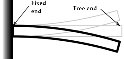
Yes the wind load is the specific case in the linked article. The "cantilever" aspect of the WTC towers is something that all towers share - in that one end is fixed in the ground, and the other end is free in the air. Like this, but sideways so the fixed end is in the ground.


My model is still cantilevered, except I did not bother to solidly fix the the base, as friction alone stops it from moving. However I might be more accurate if I did fix the base (and maybe beef up the splice plates), as the non-fixed base has (essentially) no resistance to rotating. Perhaps using a couple of bricks on either side of each column base.
 
Last edited:
I'm a bit busy today, but what do you think such a test might demonstrate/reveal?
Don't worry, it's obviously not an urgency.

Actually, I was asking you that question. You are closer to the action and can judge better whether additional magnets would make sufficiently good surface contact on both sides.

If so, I expect/predict a stronger connection between walls and floors. This would have the following effects: in a "nudge" test, the oscillation frequency will increase measurably. In a drop test, the collapse will be slowed down measurably.

I volounteer for the tracking work, of course.

Controlled variables, falsification and verification can only bring the experiment closer to the scientific method, and I bet you're a little scientifically curious too ;)
 
The comparison only makes sense when you regard the wind as blowing against it. That is like gravity pulling on a horizontal beam.

psok
Doesn't that make every high rise steel structure a cantilever beam then? Very few have columns that are single pieces of steel from foundation to roof. They are spliced sections.
 
Doesn't that make every high rise steel structure a cantilever beam then?

It does. I think the discussion about cantilevering arose from Polly's reading of the 1965 Robert E. Rapp article (attached). I think he was basically making the point that my model was not the same aspect ratio (width to height) as the towers. But I don't think that's particularly relevant - once the floors are no longer there (in my model) the tower would collapse no matter how narrow the floors were.
 

Attachments

  • The Word Trade Center - Robert E. Rapp 1965.pdf
    19.1 MB · Views: 574
Hi Mick,

the ISF's tfk is trying to organize a booth at the upcoming AIA Convention next to AE911Truth's booth, to offer some debunking to any passerbys, and he asks for ideas and contributions. I suggested that perhaps your model could be presented there:
http://www.internationalskeptics.com/forums/showthread.php?p=11259663&posted=1#post11259663

Either you (or someone) compose a video that explains in simple (for architects :D) terms what you do and what happens; or perhaps even the actual physical model to be played with live for all to see.
 
The initiative could be interesting for a couple or three reasons - not least of which is that tfk has been outspoken in his disagreement with the mechanism as a foundation for character attacking those who support it. His goals - unless he changes - would be subordinated to "Support Bazant and NIST at any cost". However even the dominant views of relatively uninformed engineers should still be good enough to rebut the usual AE911 T Szamboti, D Chandler and C Sarns arguments.

It will present an interesting policy challenge for the organisers. Presuming that they allow Gage/AE911 to present on essentially a premise of "we shouldn't be seen obstructing" THEN recognise the possibility of agro with an opposing presentation - so do they block the second comer to avoid conflict?

By doing so they stop the "good guys" and allow the "baddies".

Put even simpler - if AIA has deliberately taken the easy - non-controversial track - allow AE911 to have the booth knowing that the vast majority will dismiss the message...then the opposition could be counter productive by putting a spotlight of attention on what AIA really wanted to let die from lack of interest.

Interesting - I'll wait and see. Longer term - if it goes ahead - I see it adding to the confusion in forum discussions.
 
Last edited:
Looks like my "even simpler' version was on target. AIA has said "no!" to the potential conflict.

Originally Posted by tfk
Well, bad news, guys.

I just got a call from the AIA. After careful consideration, they have turned down my request. They were very nice about it. But my proposal didn't meet with their goals.

Or some such.
Content from External Source
Bottom line for this thread - they wont need the model in any form.
 
they wont need the model in any form.

Made me think though (and apologies in advance for this stream of thought): my model is quite large and heavy, as I wanted to reduce scaling issues a little. And while it would fit in a suitcase, it does take like 20 minutes and a ladder to assemble. This makes it a bit impractical for a roving demonstration. So video might have been more sensible - perhaps with a small section of three floors on one side for illustration.

There are also other problems with wood. It warps, the density changes over time with moisture content, and it chips and breaks with impact.

But (engaging in some wishful thinking) - what if there was a way of making a much smaller model that could also be rapidly and repeatedly assembled? The material would have to be dense (to improve scale issues) and durable (for reuse), so (again, blue sky thinking) precisely machined steel would seem like the obvious choice. This could just be stock steel cut to length. Or maybe even tool steel, which is available sized to very high tolerance, with precise corners (though rather expensive, so probably not).

Using steel instead of wood should (all other things being equal) allow for a much smaller model that gives the same result.

The tricky problem of course is the connections. I first though that magnets wold not work, as it's steel all the way down. But then I realized there's no great need to make the "columns" out of steel. Their primary function in this particular model is supporting strength, not supplying falling mass, so they could be made of something less dense.

This could even be wood again, but I think an ideal solution would be machined aluminum with magnets set in recesses so the surface of the magnet is flush with the aluminum surface (this solves an existing problem of unrealistic force transmission from impacts on the top of the metal plates, and also protects the magnets.

It would also be great to get away from magnets entirely. I keep thinking there must be a sensible alternative out there. Something that's either so cheap you can replace it with every usage, or something that can be "reset" every time.

A connector needs to:
  1. Provide sufficient vertical support to not fail with the sudden application of the weight of six floors.
  2. Provide resistance to tension, to give the walls lateral support by holding them in place. (i.e. simply placing the floors on a breakable shelf would not work)
  3. Provide moment resistance. i.e. resistance to rotational forces. Although the original floors did not do this as part of their specification, having it here gives back some of the function of the missing sides of the building (the Vierendeel truss aspect). If this is not in the connections it would probably need to be simulated in some other way, perhaps with a rear shear plate).
  4. (Ideally) fail suddenly with little prior displacement.
  5. (Ideally) fail in a way that leaves the wall surface free of immovable obstacles.
One thing I keep coming back to is recessed ("concealed") cabinet door hinges
20160504-081635-nvjwl.jpg
These snap to two positions: flat or angled. I'd considered (with the wood model) having them embedded in the side walls, the you could snap them up to form the "seat", and provide tension by hooking in the floors somehow.

Not really very practical though, it's difficult to create the accurate recesses, and the hinges themselves are way more expensive than magnets.

However, I feel there must be something out there that's small and cheap that provides similar functionality. Essentially I'm looking for a bistable structure (of which the cabinet hinge is a complex example), the most common simple example of a bistable structure is a slap bracelet. Another example is a toggle switch (purely from a mechanical perspective), or an animal trap.

Anyway, enough rambling.
 
Here's a simple schematic of the bistable structure idea (lacking any tension component though)

20160504-090115-vlxhn.jpg
The "Seats" are like toggle switches, but without a restraint on the bottom, so the arm could flip totally out of the way (ideally into a recess).

I say bistable, but really it just need to be "monostable + not there"

There must be some really simple cheap widget that I could use for this. Something that snaps into one position, and then snaps away into either another, or a free state.
 
Yes. Do you understand that the side in the model is vertically consistent where the towers were not ?


No. The mechanical floors were below the top 11 floors and that was where the real weight of the mechanical equipment was, that's why the floors were twice as thick there. The sides on the model should get lighter as the height increases is what I am saying. I think that's relevant to what is being done.


Well those are your thoughts.


You could just as easily say that the middle of the sides were weaker if that sits more comfortably. They would in neither case present a consistent resistance along their length is the point that I am making. I think that could be replicated here.


The core column structure is not there for the edges of the floor to tie into in the corners of the twin towers. This means that when you look at a floor of the tower from any side the floor truss system will be TRANSVERSE/CORE/TRANSVERSE on the inside.

This is not accurate.

The towers corners were not stronger than the 4 sides... one could argue that they were weaker. They carried no loads actually!

There was heavy equipment on the top mech floors including elevator machinery, radio transmitters., tanks, HVAC equipment. The mech floors were 6" slabs and the framing was standard wf beams and girders.
 
No that's not what I said. I said the tower was in effect a cantilever beam.

Only as far as resisting wind shear... Your slenderness ratio tack is all wrong.

Mick's model illustrates a progressive floor collapse when the dynamic load exceeds the connection capacity of the slab to the columns. This was not the only mode of floor failure... slabs broke as well as their connection to the columns. Mick's model does not illustrate that.

The only important thing for a progressive collapse is to have enough similar floors so that once a threshold dynamic load presents... the floor collapse is unstoppable and inevitable. All the office floors for the entire height were identical structurally... the columns obviously become stronger as you move down because of total load is aggregating. The mech floors, though stronger would also have a threshold at which they would break... and that threshold was exceeded.
 
It'd the lid on the box. An outrigger truss joining core and outer columns.

There were 8 of them and they connected at 8 points in a 832 long facade.

The various grades of steel were used in the facade because they were size constrained... not so in the core.
 
I still do not see this vertical structure as a cantilever 'beam'.
Why are you so utterly recalcitrant to draw an illustration of the points you are trying to make?

As far as scaling the ratios of height, width and floor spacing goes, gravity WILL NOT scale down as well.

He's completely wrong about the cantilever. YES it is a cantilever as far as horizontal loads such as wind or a plane hitting the tower.. so is a telephone or flag pole... but as far as gravitational collapse he's spouting nonsense.
 
Only as far as resisting wind shear... Your slenderness ratio tack is all wrong.

Mick's model illustrates a progressive floor collapse when the dynamic load exceeds the connection capacity of the slab to the columns. This was not the only mode of floor failure... slabs broke as well as their connection to the columns. Mick's model does not illustrate that.

The only important thing for a progressive collapse is to have enough similar floors so that once a threshold dynamic load presents... the floor collapse is unstoppable and inevitable. All the office floors for the entire height were identical structurally... the columns obviously become stronger as you move down because of total load is aggregating. The mech floors, though stronger would also have a threshold at which they would break... and that threshold was exceeded.

The argument that the mech floors were stronger and thus better able to halt collapse, seems to ignore the fact that they were stronger ,,, for a reason. They had greater floor loading BECAUSE they were mech floors. Perhaps the difference between design load and actual load might also be greater, probably was imho. Once a mechanical floor does fail though, you now have all that relatively dense and heavy machinery ploughing down through the rest if the structure.
 
The argument that the mech floors were stronger and thus better able to halt collapse, seems to ignore the fact that they were stronger ,,, for a reason. They had greater floor loading BECAUSE they were mech floors. Perhaps the difference between design load and actual load might also be greater, probably was imho. Once a mechanical floor does fail though, you now have all that relatively dense and heavy machinery ploughing down through the rest if the structure.
The mech floors had a higher super imposed live load rating... and they were really 2 story spaces with a mezzanine. But they were 20 stories below were the collapsing floors were coming from and so were seeing more than enough dynamic load to fail in a NY moment. No chance for arrest.
 
A chance for arrest was not my point.

Point is that greater live load is there because those floors had need of a greater capacity for live load. Truthers seem to believe that these floors were empty and therefore that extra capacity was available to resist collapse. It wasn't.
 
I just ran across this video. The guy's bias is revealed with lines like
the 9/11 Commission "was set up to fail" :rolleyes: and such...so I took his narrative with a grain of salt...
but was intrigued to see his backyard experiments, re. Mick's approach to a physical model...

[edit: p.s. It's about 14 minutes...in that time he tries a few different models]


He supports CD and thermite without evidence. I would hate to see the explosives in his last "experiment" sized to real size. He is implying it took explosives to do it, and ignores the his supersonic shock waves from firecrackers which did not happen on 9/11. He runs a business, and is a sewer engineer. It is sad to include quote mines like "set up to fail", and ignore the FBI did the biggest investigation in history.
If he could tailor his models to include 12 floors falling would make the lower floor fail, like WTC tower structure, then his models would not support his CD theory.
 
I just ran across this video. The guy's bias is revealed with lines like
the 9/11 Commission "was set up to fail" :rolleyes: and such...so I took his narrative with a grain of salt...
The whole presentation is propagandist nonsense targeted at a very unsophisticated audience. It is hard to believe that any qualified engineer could honestly make the claims that Cole presents.

He introduces the "models" section with a straw-man false reference to the early FEMA suggestion that the initiator of Twin Towers collapses was by "pancaking". (Note that it was "initiation" NOT "progression" - the difference subject of much mendacity over the years.)

He then follows with 6 models - 2 thru 6 of which misrepresent the collapse mechanism as "column crushing" when the real event was "column bypassing" AKA "ROOSD" AKA "Three Mechanisms" etc which is the real 9/11 mechanism which has been modelled by Mick. And the distinction has been the cause of much confusion and is still subject of feigned controversy because it was/is the most misunderstood aspect of Bazant's early paper (B&Z 2002) and IMO a fundamental error in B&V 2007.

Here they are (Ignoring the introductory straw-man reference to FEMA and "pancaking"):
1) The tall tower somewhat reminiscent of Mick's model - measures failure of floor slabs in bending. Not the mode of real event collapse.
2) The Bazant and Verdure "crush down/crush up" ["CD/CU"] model from the 2007 paper. A column crushing model not representative of real event collapse. I claim B&V does NOT apply to WTC - details if asked for. I've been subjected to insults and personal attacks for "lèse majesté" over that one for some years (daring to disagree with Bazant - the "god" of debunkers.). Cole happens to be right IMO - the Bazant & Verdure "CD/CU" model is wrong - does NOT apply to WTC Collapses. At least three "proofs" available if anyone is interested.
3) Cole's modelling of B&V "CD/CU" - not representative of WTC real event collapse.
4) Coles "paper loops" as substitute columns - possibly "borrowed" unacknowledged from psikeyhackr. Same issue - columns "in-line" not representative of WTC real event collapse.
5) Coles sets fire to the paper loops. Still "columns in line" - the "fire" is ridiculous - no further comment needed IMO.
6) Coles inserts "explosives" (fire crackers) Also "columns in line" - Insulting to any audience IMO.

Bottom lines:
(A) None of Coles models is a model of the real event and all can be dismissed on that fact alone.
(B) The biased and propagandist style should be obvious;

AND

(C) Mick modelled the real event just as I have explained it in both picture and words.

...but was intrigued to see his backyard experiments, re. Mick's approach to a physical model...
A lot of effort...

...misdirected in the case of most members here ....BUT....

Mick's model is right - all six of Cole's are wrong - they do NOT model the WTC Twin Towers 9/11 collapses..
 
Last edited:
He runs a business, and is a sewer engineer. ....
Some "sewer engineers" are good at engineering - just like some ex USAF pilots.

In fact I was a water AND sewer engineer. There is only <4% difference - well within the margin for most structural stuff. BUT I could tell the difference.


:rolleyes:
 
Back
Top