Thermal expansion of beam K3004, integrated instantaneous vs. mean coefficient of thermal exp

Mick West

Administrator
Staff member
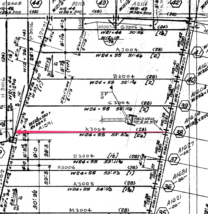
In World Trade Center 7, beam K3004 is thought to have expanded, and pushed Girder A2001 to the west. There is some dispute as to how much it could have expanded.


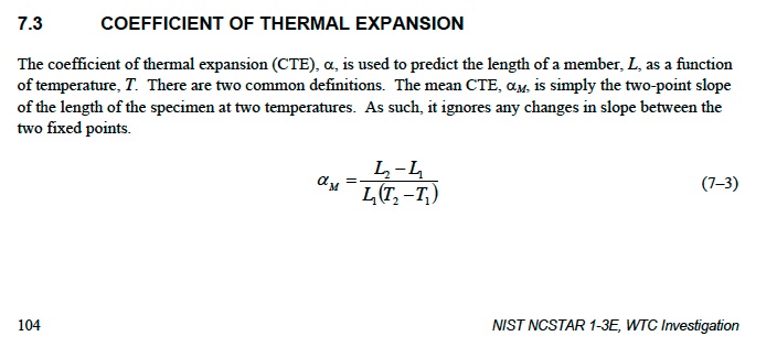
NIST NCSTAR 1-3E was focused on the WTC1/2 steel, however the findings regarding thermal expansion were carried over to the WTC7 investigation.


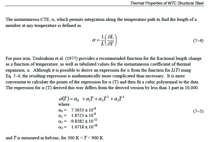
20C to 600C is 293K to 873K

Integrating the above polynomial over that range.

http://www.wolframalpha.com/input/?i=integrate (0.0000073633 +0.000000018723*x-0.0000000000098382*x^2+1.6718E-16*x^3) where x from 293 to 873


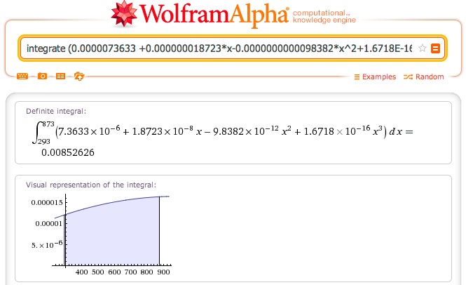
Gives 0.00852626, which we can multiply by the length of the girder, 53'8", or 644", to give 5.49"

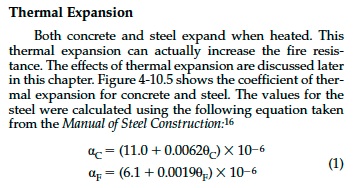
NIST also gives the AISC recommendation:


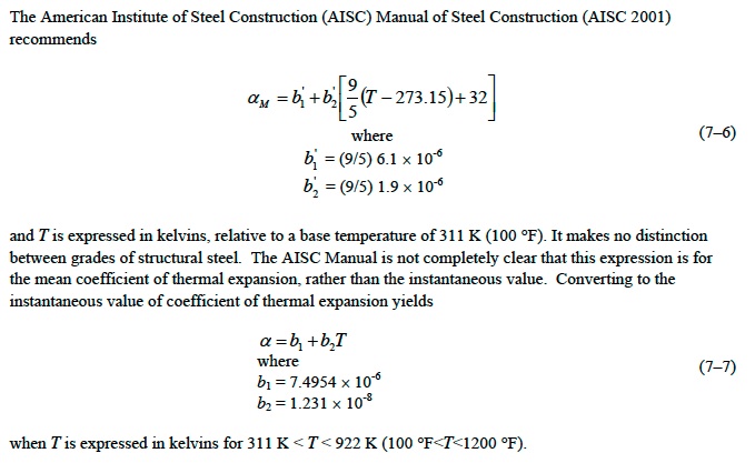
Which is a straight line, but can still be simply integrated for convenience:
http://www.wolframalpha.com/input/?i=integrate (7.4954e-6 + 1.231e-8*x) where x from 293 to 873


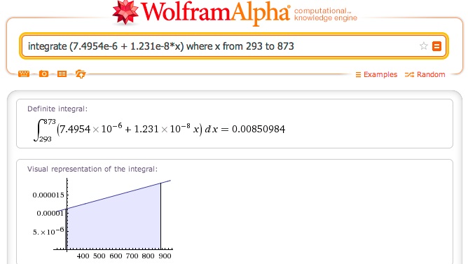
.00850984*644 is 5.48"

NIST also give the following chart of the expansion coefficient curves from various sources. The thick blue line is the polynomial used in the integration above, and the thick green is the AISC recommended value.


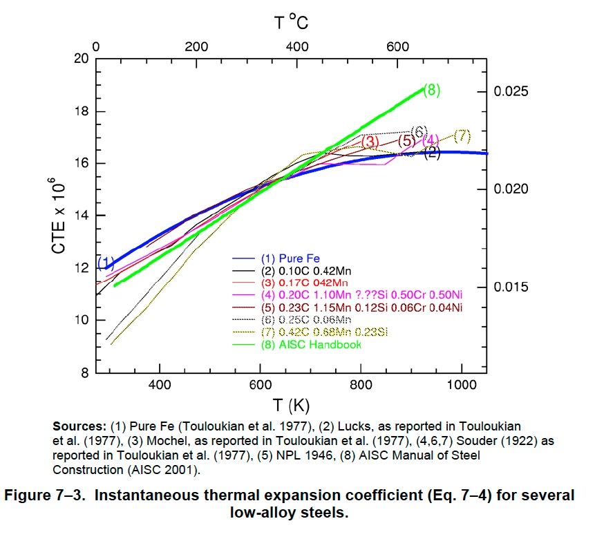
It's not entirely clear from the diagram, but it looks like some of those would give values slightly above 5.5"
 
Last edited:
Is

20C for ambient? Bit low maybe.

You used 70F, 21C. Seems close enough given the 600 cut off is a bit arbitrary.


Sorry if you covered this before, but why do you subtract 4" from each beam length?
 
Last edited:
You used 70F, 21C. Seems close enough given the 600 cut off is a bit arbitrary. Sorry if you covered this before, but why do you subtract 4" from each beam length?

Where are you taking the lengths from, E12/13?
 

Attachments

  • steelstructures3004.png
    563.9 KB · Views: 721
Yes, so using 640.69 gives 5.46 and 5.45 for the two methods above.

I have attached the CTE of ASTM A572 structural steel over the temperature range. It is not constant.


Using the attached graph and taking the CTE at room temperature (70 deg. F) to be 6 x 10e-6 in/in-deg F and 8 x 10e-6 in/in-deg F at 1,100 degrees F for ASTM A572 steel, I interpolated the CTE at each degree over a range of 70 to 1,112 deg. F (21 to 600 deg. C). I used a beam length of 644.6875 inches, which would include the brackets for the beam to the girders on each end of the beam.

With the equation delta L = L x CTE x delta T in one degree increments, and adding the delta L to get a new length before calculating again at the next temperature, I get 4.75". This is also conservative as there would be some shortening due to beam sagging that is not considered here.

Don't know what you are doing but you are not getting the right answers. The NIST calculations were also wrong if they got 5.5" for beam K3004 heated to 600 degrees C.

I have also attached my spread sheet.
 

Attachments

  • CTE of ASTM A572 steel over temperature.pdf
    13.6 KB · Views: 1,007
  • Beam expansion (stepped cte).xlsx
    92.9 KB · Views: 1,080
Last edited by a moderator:
It's not constant. But it's not linear either. Your graph indicates a linear rate of change of CTE, so it's wrong.

And where do you get these 6 and 8 figures from? They are suspiciously low in significant figures.
 
It's not constant. But it's not linear either. Your graph indicates a linear rate of change of CTE, so it's wrong.

And where do you get these 6 and 8 figures from? They are suspiciously low in significant figures.
The graph is from a published thesis from Worcester Polytechnic Institute. They are generally considered to be quite knowledgeable about heating effects on structures.

The significant figures you speak of will not get you to the 5.5" you claim.
 
Attached is the K3004 expansion with sagging and shortening considered. This was done by David Chandler and myself last year.

The shortening was done using both standard trigonometry and by calculating the arc the sagging generates and finding the shorter chord. The second method is more accurate. However, they are close and both show an expansion of about 4.5" for a 644.6875 inch ASTM A572 steel beam like K3004 with a standard floor load at 600 degrees C when sagging induced shortening is considered. The AISC elastic modulus retention factors at elevated temperatures were used to calculate sagging at each temperature. The maximum possible expansion at any temperature is about 4.75", since above about 649 degrees C the shortening is greater than expansion.
 

Attachments

  • K3004 expansion with sagging considered.xlsx
    38.9 KB · Views: 836
Could it be that Mick is making the same mistake that I did initially, by not using an average CTE.

When first attempting these calculations I applied the final temperature CTE incorrectly rather than one that is scaled over temperature as in Tony's increasing temperature Excel sheet. Just a thought.

Interestingly perhaps NIST did that too as they also got to 5.5" as did Mick.

Although they don't show the 5.5" beam expansion calculation they do for other expansions, like that of the girder to show it would break its bolts on page 344 of NCSTAR 1-9, and they incorrectly use a constant CTE and take the delta T as 600 degrees C when it should have been 579 degrees C if they went from room temperature to 600 degrees C.

To get 5.5" the NIST calculation had to use a constant CTE of 8.18 x 10e-6 in/in-deg F and an 1,112 deg. F (600 degree C) delta T. We know that is not correct if the CTE is not constant over the temperature range, where it is 6 x 10e-6 in/in-deg F at room temperature and somewhere in between up to 1,112 degrees F (600 degrees C), and the delta T is from room temperature up to 1,112 deg. F (600 degrees C).

However, Mick seems to know it should be integrated (averaging is just a quick way to do it, but not quite as accurate if the delta L isn't added at each step).

Let's hear what Mick has to say about what he is doing. I kind of feel sorry for him, as he has quickly run into a brick wall trying to defend the NIST WTC 7 report here against the unambiguous and clear evidence that they omitted very pertinent structural features from their analysis (girder stiffeners and beams stubs), which when included in the analysis falsify their hypothesis, and now we are quickly showing him they didn't even do the thermal expansion right. Most of us realized the reports were not accurate, and very likely done to support a fraudulent political meme, over a much longer period of time, and I would imagine it is difficult to accept in a short time frame.
 
Last edited:
If something has a nonlinear rate of change, then you need a touch of calculus to really understand it. Tony's calculations are linear. Mine (and NIST's) are nonlinear.

My calculus is so rusty it's growing iron microspheres. But I'll get to the bottom of this.
 
If something has a nonlinear rate of change, then you need a touch of calculus to really understand it. Tony's calculations are linear. Mine (and NIST's) are nonlinear.

My calculus is so rusty it's growing iron microspheres. But I'll get to the bottom of this.
Mick, you would need an equation for the CTE of ASTM A572 steel as a function of temperature to use calculus, and I don't see where you have provided one. Luckily for you there is no need, as the Worcester Polytechnic CTE chart for this material, that I provided here, is correct. The CTE of ASTM A572 steel is non-constant but linearly increases with temperature.

There is no chance you will be able to show a 644.6875" long ASTM A572 steel beam taken from room temperature to 600 degrees C will expand more than 4.75".

The NIST calculation method for thermal expansion (shown on page 344 of NCSTAR 1-9) was shown to be incorrect here on the grounds that they used a constant maximum CTE, when it is not for the material in question (ASTM A572 structural steel). It is hard to understand why you think you can salvage their 5.5" of expansion calculation by using a non-constant CTE like I did and then applying calculus when you don't even have an equation to use it on and aren't even sure how to go about it.
 
Last edited:
Aha, I believe I see the error Tony. You assumed the coefficient was instantaneous, when it was actually mean.

The graph from 0.6 to 0.8 you use is from Andrea Arakelian's phd Thesis (attached), and it's generated using the equation:
α = (6.1+ 0.0019T) ×10^−6, which is taken from The SFPE Handbook of Fire Protection Engineering.

This is exactly the same equation as NIST used, see 7-6 below, it's just converted from F to K.
upload_2013-10-21_9-13-56.png


Note the "m" there. And also note that NIST says "The AISC Manual is not completely clear that this express is for the mean coefficient of thermal expansion, rather than the instantaneous" - so they are describing there why people make that mistake.

Looking in SFPE, they actually get their equation from AISC (1980 edition). Also of note: it's a generic equation for any steel, not specifically A572.


Note the vertical scale of this graph is dL/L (the total fraction of change, the dilatometric ratio), not the CTE. (It's the mean CTE times temperature under the linear model, or the integrated instantaneous CTE). They explain this terminology here:


""
 

Attachments

  • arakelian_thesis.pdf
    982 KB · Views: 1,856
Last edited:
It seems to me that Andrea Arakelian in her thesis referred to by Mick didn't use 'generic' steel at all. She quotes data for ASTM A572, Grade 50 Steel.

And she also shows the co-efficient for that steel as linear within the temperatures we are discussing.

Mick quotes 4-10.5 above. That also shows a straight line until 1200F at which the co-efficient rises more rapidly.

This is Andrea's Table from page 34 ( pdf page 47 ) :-

Table 3.3.2-1: Temperature Effects on Mechanical Properties of ASTM A572, Grade 50 Steel

Steel Temperature Steel Properties

°C °F θ value σy (psi) E (psi) α (in/in°F)
0 32 -0.02 50,780 28,976,336 5.9708E-06
20 68 0 50,000 29,000,000 6.0392E-06
30 86 0.01 49,610 28,994,084 6.0734E-06
40 104 0.02 49,220 28,976,336 6.1076E-06
50 122 0.03 48,830 28,946,756 6.1418E-06
100 212 0.08 46,876 28,621,376 6.3128E-06
150 302 0.13 44,903 28,000,196 6.4838E-06
200 392 0.18 42,881 27,083,216 6.6548E-06
250 482 0.23 40,766 25,870,436 6.8258E-06
300 572 0.28 38,499 24,361,856 6.9968E-06
350 662 0.33 36,009 22,557,476 7.1678E-06
400 752 0.38 33,210 20,457,296 7.3388E-06
450 842 0.43 29,999 18,061,316 7.5098E-06
500 932 0.48 26,264 15,369,536 7.6808E-06
538 1000 0.52 22,994 13,125,952 7.8108E-06
550 1022 0.53 21,873 12,381,956 7.8518E-06
600 1112 0.58 16,686 9,098,576 8.0228E-06
650 1202 0.63 10,543 5,519,396 8.1938E-06
700 1292 0.68 3,275 1,644,416 8.3648E-06

You will see above where I have highlighted the temperatures involved and the co-efficients at those figures.

If you then check the table you will find that the co-efficient rises at 0.0019 per degree F throughout that table (at the temperatures involved.) Perfectly linear.

And as Tony used such a rising co-efficient and added each added length to the next degree calculation, and so on, then I really can't see how his end result would be far off.
 
Here's another source that explains the difference. The EPRI Carbon Steel Handbook


5.1 Physical Properties

The following physical properties have been compiled from several

publications [6, 8, 17, 18]:

Mean coefficient of linear thermal expansion: the ratio of the change
in length to the original length at a reference temperature, T0, per
degree of temperature change, where T0 is normally room
temperature. If l0 is the length at T0 and alpha (α) is the mean
coefficient of linear thermal expansion, the length at temperature T,
lt, is given by

lt = l0[1 + α(T-T0)] Ref [19]

Instantaneous coefficient of linear thermal expansion: the rate of the
change in length at a specific temperature.
Content from External Source
Table 5-2 there confirms the values you are using were for the mean, and not instantaneous


Attachments

  • 174413923-28247782-Carbon-Steel-Handbook.pdf
    2.7 MB · Views: 191,645
Last edited:
It seems to me that Andrea Arakelian in her thesis referred to by Mick didn't use 'generic' steel at all. She quotes data for ASTM A572, Grade 50 Steel.
She labels it like that yes, but she's just using the AISC generic formula, which is not steel specific.

And she also shows the co-efficient for that steel as linear within the temperatures we are discussing.
Because she uses the generic formula. It's an approximation, not what actually happens. But the non-linearity in not Tony's key mistake here

And as Tony used such a rising co-efficient and added each added length to the next degree calculation, and so on, then I really can't see how his end result would be far off.
It's because he used the mean value as an instantaneous value. The integration is already done for the mean value, so you just use it directly to get the total.
 
Mick. In your first post on this new thread you show NCSTAR 1-3E. page 104 second para. :- " the expression for alpha (T) derived this way differs from the derived version by less than 1 part in 10,000.

Are we in danger of arguing about how many angels can dance on a pinhead here ?

4.75" or 5.5" Both are only half the distance required.
 
Mick. In your first post on this new thread you show NCSTAR 1-3E. page 104 second para. :- " the expression for alpha (T) derived this way differs from the derived version by less than 1 part in 10,000.
That's just explaining the variance of the polynomial from the more complex equation derived from actual data. It's neither here nor there.

Are we in danger of arguing about how many angels can dance on a pinhead here ?

4.75" or 5.5" Both are only half the distance required.

The broader argument is that NIST made several mistakes. One "mistake" mentioned by Tony was:
Although they don't show the 5.5" beam expansion calculation they do for other expansions, like that of the girder to show it would break its bolts on page 344 of NCSTAR 1-9, and they incorrectly use a constant CTE and take the delta T as 600 degrees C when it should have been 579 degrees C if they went from room temperature to 600 degrees C.

To get 5.5" the NIST calculation had to use a constant CTE of 8.18 x 10e-6 in/in-deg F and an 1,112 deg. F (600 degree C) delta T. We know that is not correct if the CTE is not constant over the temperature range, where it is 6 x 10e-6 in/in-deg F at room temperature and somewhere in between up to 1,112 degrees F (600 degrees C), and the delta T is from room temperature up to 1,112 deg. F (600 degrees C).

So in this instance it turns out that Tony was wrong about how to use the CTE, and NIST were right. Tony did not realize the value was a mean. NIST did.
 
Last edited:
And another:
Designers' Guide to EN 1991-1-2, 1992-1-2, 1993-1-2 and 1994-1-2: Handbook ...
By Tom Lennon, D. Moore
http://books.google.com/books?id=_4Cxwc25gOwC&lpg=PA39&ots=OFyUjLtUae&dq="thermal elongation of steel"&pg=PA40#v=onepage&q&f=false


This actually gives an equation 6.1a, for the slight initial curve in dl under this standard.
dl/l = 1.2e-5*t+0.4e-8*t^2-2.416e-4
Substituting t=600 gives dl = 0.0083984, expansion of 5.41"

This equation is repeated here:
Fire Design of Steel Structures: Eurocode 1: Actions on structures; Part 1-2 ...
By Jean-Marc Franssen, Paulo Vila Real
http://books.google.com/books?id=mY2s7qd_XEsC&lpg=PA321&ots=dZnJx4xmfX&dq="thermal elongation of steel"&pg=PA321#v=onepage&q&f=false

And here:
Designing Steel Structures for Fire Safety
edited by Jean Marc Franssen, Venkatesh Kodur, Raul Zaharia
http://books.google.com/books?id=QLqCtEMGxyEC&lpg=PA151&ots=4jomMzrubx&dq="thermal elongation of steel"&pg=PA151#v=onepage&q="thermal elongation of steel"&f=false

The original source of this equation is
Eurocode 3: Design of steel structures - Part 1-2: General rules - Structural fire design 1995
https://law.resource.org/pub/eur/ibr/en.1993.1.2.2005.html
 
Last edited:
Can you get it to NIST's 'typo' figure of 6.25" so that it would drop from a 12" seat ? Or to min 9" when stiffeners are in place ?
No, and I said that in post #2.

The point here is that there's quite a big error in the figures used in your videos. This thread is about YOUR error, not NIST's error.
 
Keep on topic please (OT post removed). The issue here is simply how much science tells us the beam would have expanded at 600C, and if there's an error in Tony's (and/or gerrycan's) calculations of this.
 
Last edited:
You've read the thread, so you can see it says 5.5" at 600C. Do you agree?

When I first became exposed to this 'walk-off' debate I went away to check the formulae and calculation methods. I then simply applied the on-line data available and, using a handheld calculator, confirmed the expansion at circa 5.5".

Then, I realised that I had used the final temperature instead of the rise in temperature ( Delta T ) That reduced my figure slightly to 5.35".

The formula was simply - Original length x Delta T x coefficient = Expansion.

The coefficient for that grade of steel, from an average of around five source documents, was 0.00000805 at 1112F ( 600C ), and with length of the girder at 640.69" the calc was :- 640.69 x 1043 x 0.00000805 = 5.35".

Then the concept of 'average coefficient' was introduced to me and I went back to basics again.

As the formula used Delta T then it was clear to me that a step by step process could be used. I used the formula to check expansion from ambient to 300C ( 572F ) as follows :-

640.69 x 502 x 0.0000069968 = 2.25" ( new length 640.69" + 2.25" = 642.94" )

Then I applied the formula and coefficient for a further rise from 300C ( 572F ) to 500C ( 932F ) as follows :-

642.94 x 360 x 0.0000076808 = 1.78" ( new length 642.94" + 1.78" = 644.72" )

Again from 500C ( 932F ) to 600C ( 1112F ) as follows :-

644.72 x 180 x 0.0000080228 = 0.93" ( new length 644.72" + 0.93" = 645.65" )

Thus I had staged the event from ambient to 600C ( 1112F ) over three seperate calculations using Delta T logic and the new coefficient for each seperate event, and got final length 645.65" - an increase from 640.69" of 4.96".

As this was less than the 5.35" achieved by going in one stage from ambient directly to 600C in my initial simple calculation it indicated that using three stages had had a reducing effect. That led me to consider that if I had staged the calcs over 1042 stages representing each single degree F from ambient to 1112F then a further reduction would probably be seen.

Then, along came Tony S's Excel sheet that demonstrated that effect clearly, as he had indeed programmed his spreadsheet to calculate every degree F increase seperately, and add the incremental length increase to the next calculation. As he also used the coefficient relevent to that new temperature as per all the on-line information then no matter how you look at it - it takes some undermining to disprove it.

Soooooo. To answer your question. I originally agreed that 5.35" seemed to be the solution, but subsequent personal work, and input from others seem to negate that.

Quite where the two methods of calculation differ is beyond my skill level, but differ they do. Seems to me that applying a very large Delta T results in a larger increase in length than by applying over 1000 seperate tiny Delta T's.
 
You've read the thread, so you can see it says 5.5" at 600C. Do you agree?
If it is true that 8.2 in/in-deg F is the mean CTE at 1,112 degrees F (600 degrees C) then the NIST expansion value of 5.5 inches for a 644.6875" long beam would be correct. From the chart you show the mean would be for room temperature up to the temperature in question.

Most CTE values are not already integrated and one is advised to use an average over a range.

If this is true, you have won one out of four in your defense of the NIST report, but it becomes a moot point because they still have not explained how they get enough expansion to go 6.25" with the admission that the girder seat is 12" wide, and they still haven't even commented on the omission of the girder stiffeners and beam stubs.
 
Quite where the two methods of calculation differ is beyond my skill level, but differ they do. Seems to me that applying a very large Delta T results in a larger increase in length than by applying over 1000 seperate tiny Delta T's.

Yes it does, but the point you are missing is that the mean coefficient IS the average coefficient. So if your mean coefficient was 0.00000805, then that's the value you use.
 
Yes it does, but the point you are missing is that the mean coefficient IS the average coefficient. So if your mean coefficient was 0.00000805, then that's the value you use.

As I said, that was what I did originally. But that still doesnt explain why using over 1000 seperate Delta T calculations results in a lower overall expansion than using just one.
 
If it is true that 8.2 in/in-deg F is the mean CTE at 1,112 degrees F (600 degrees C) then the NIST expansion value of 5.5 inches for a 644.6875" long beam would be correct. From the chart you show the mean would be for room temperature up to the temperature in question.

Most CTE values are not already integrated and one is advised to use an average over a range.

If this is true, you have won one out of four in your defense of the NIST report, but it becomes a moot point because they still have not explained how they get enough expansion to go 6.25" with the admission that the girder seat is 12" wide, and they still haven't even commented on the omission of the girder stiffeners and beam stubs.

I think that given other sources having matching figures, in particular the almost exact match with the Eurocode equation (which use the simpler to understand elongation ratio) it is pretty conclusive that 5.5" is correct.
 
As I said, that was what I did originally. But that still doesnt explain why using over 1000 seperate Delta T calculations results in a lower overall expansion than using just one.

It's because 999 of those 1000 calculations used smaller coefficients.
 
If this is true, you have won one out of four in your defense of the NIST report, but it becomes a moot point because they still have not explained how they get enough expansion to go 6.25" with the admission that the girder seat is 12" wide, and they still haven't even commented on the omission of the girder stiffeners and beam stubs.

Yeah, all debunked 9/11 Truth points immediately become moot points. :)
 
It's because 999 of those 1000 calculations used smaller coefficients.

Of course they do - in increments of 0.000000002 per degree F. From 0.000006 at 70 F through to 0.000008084 at 1112F. The only explanation that I can think of concerns a thousand small losses over decimal points involved that add up to the difference seen. Either that, or the coefficients are not an integrated mean after all. I await the definitive answer with interest.
 
Last edited:
Of course they do - in increments of 0.000000002 per degree F. From 0.000006 at 70 F through to 0.000008084 at 1112F. The only explanation that I can think of concerns a thousand small losses over decimal points involved that add up to the difference seen. Either that, or the coefficients are not an integrated mean after all. I await the definitive answer with interest.

It's a bit like you are asking why a triangle has a smaller area than a square of the same height. Think about it again, look at the numbers, draw a graph. Sorry I can't explain it better, maybe ask Tony.
 
Back
Top