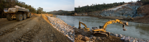
Looking at the photos posted above of the post-shutdown state of the end of the upper spillway, together with a few more from DWR's most recent photo uploads, there's something that may be pretty telling about the state of the spillway foundation. This is best illustrated by reference to the photos themselves.
Before the last shutdown, I understood Mr Croyle of DWR to say that it was intended to "shotcrete" the whole area of the splash pool. In the event that's not what happened and instead the face of the remaining spillway end rock foundation was what got the shotcrete treatment. The discrepancy actually makes sense if before the work started the decision was made to fill the splash pool with concrete as part of the final remedial effort.
But for some reason shotcrete was applied to a surface area that can be seen in the photos below, which is too large just to be overflow or excess from the rock foundation face. It lies on the extreme left of that area:
View attachment 26117
View attachment 26118
Before it was covered over, this area lay below what looks like a large cavity under the spillway deck. Below it is lot of fragmented rock/rubble, which I supposed when I saw this photo might have been washed out from under the deck when the spillway was running. That by itself would tend to indicate some considerable volume of water under the deck that was not being caught by the drainage system (despite the amount of water that was seen being discharged from the drains that emptied on to the deck):
View attachment 26121
Looking at the post-shutdown photos there's a perhaps rather telling feature evident, shown in this close-up. The shotcrete applied in the area forms a barrier or maybe a "crust" over part of it, which indicates that it prevented erosion of what was underneath, but to the near side of that area a deep gully has formed:
View attachment 26122
There must have been a natural fissure in the rock there to start with; this one looks as big as some of those that caused such concern when the attempt to use the emergency spillway was made. Although DWR is carrying out a geological survey of the area, at the moment there's reason to think that whole area is riven by features like this - and perhaps right up to the area of the spillway gates. Of course the Board of Consultants has recommended the reconstruction of both the remaining upper and lower spillway sections. You can see why if large parts of the structure were originally founded on ground like this. They'll be needing an awful lot of rock and concrete to do the job.