Oroville Dam Spillway Failure

Status
Not open for further replies.
The spacing between the fence posts on the spillway sidewalls is actually 10' between posts.

There is an entire parallel thread looking at these details.

EDIT
added the link to the thread

https://www.metabunk.org/oroville-dam-drains-in-the-spillway-walls-how-do-they-work.t8407/
Yes, I have been following that thread and in the lower section, I would agree with you. However, in the upper section it appears that the fence has poles more frequently (perhaps due to the risk of junk coming through the gates, or idiots trying to go over it?).
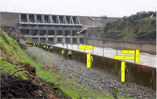
Here is an annotated version of the picture you posted showing the workers on the spillway (from
http://pixel-ca-dwr.photoshelter.co...Ip7IY/KG-oroville-damage-13013-02-20-2017-jpg originally) I made a box the same height as the workers (for boxes 1 and 2) and the same height as the fence (box 3) then I copied the boxes and rotated them to match the angle of the fence posts:
Spillway fence.png
The distance is not going to match due to the perspective, but if the fence is 3-4' tall and the workers are 5'-6' tall, the posts are not 10' apart in THIS section (it looks like it may change spacing at the R10 mark).
If you look at the other pictures from today, they show the same spacing.
Here is one that you included that shows the close spacing of the posts hear the gates:


Here is another from the Pixle site showing a closeup of the fence where it appears that you can see the spacing change (I put a red line at each post):
Source: http://cdn.c.photoshelter.com/img-g...flwefms2040ed20170224o4_MQ.LCnWXvT5Y/fit=1040
KG_oroville_damage-13075_02_20_2017.jpg


Aaron Z
 
So you are just seeing spray from the initial drop, then more spray where it bounces off the big rock lower.

I've also concluded that's the explanation after seeing what were definitely two plumes, but in addition there are foreground obstructions (trees) that give the illusion of separation:

Spray(s).jpg

The image on the right illustrates how high these plumes can go but perhaps more interesting is that they don't appear at any regular intervals. I don't know the velocity of the water coming down the spillway or indeed whether the speed/volume of it varies and whether that would account for these random events.

However, the last live images I saw of the "waterfall" (2 days ago) showed a massive volume of water hitting the rock surface that was formerly under concrete and then passing mostly into the big channel that has opened up to the side of the large rock outcrop. That channel must be a maelstrom and I imagine that accounts at least in part for what we can see.
 
Last edited by a moderator:
The image on the right illustrates how high these plumes can go but perhaps more interesting is that they don't appear at any regular intervals. I don't know the velocity of the water coming down the spillway or indeed whether the speed/volume of it varies and whether that would account for these random events.
Yes, there's large random splashes like this. Check here aroudn 0:27

Source: https://youtu.be/D5t52UiRZj0?t=27s
 
New photos posted at the DWR site, including night work - appears they are filling in across the emergency spillway face with the grouted rip-rap.
upload_2017-2-21_16-18-31.png


Where they are drilling there (and later concreted) is where there was a kind of natural notch where water flowing along the "apron" ran off. They probably identified it as a key point that needed strengthening
20170221-144822-3kll4.jpg

There also seems to have been a tree growing there.
20170221-144934-ec933.jpg
 
Thanks Anna.
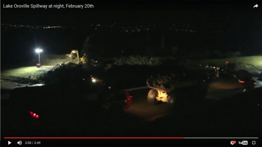
At 2:00 in the night video (Source: youtu.be/VILY-e6V_Xk ), you can see what may be an excavator working on a road down to the side of the spillway closest to the emergency spillway:
PathDownslope.JPG

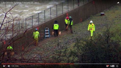
Here is an excellent shot of the chainlink fence near the gates (from 1:27 in the day video that Anna posted: https://youtu.be/HpijVhHAngM ):
Spillway fenceFromVideo.jpg
No way that is 10' spacing in that section.

Aaron Z
 
Where they are drilling there

The excavator on the right has a large hydraulic breaker (essentially a large paving breaker) on its boom. They appear to be removing some of the rock at the base of the weir. This is the first I have seen them removing rock.
 
Thanks Anna.
At 2:00 in the night video (Source: youtu.be/VILY-e6V_Xk ), you can see what may be an excavator working on a road down to the side of the spillway closest to the emergency spillway:

Well spotted in that video clip, and thanks to Anna R. for the original links.

These are impressively well produced videos from DWR - but with no commentary whatsoever, spoken or by way of subtitles, so you have to look to their media briefings for any real explanation of what's going on. I can't say that from these I have gained any clear insight into what caused the main spillway collapse or exactly what they plan to do to repair it. I suppose this might be information/expectation management on their part but I can't make that accusation on mere inference. Anyway we'll get a better idea when they next shut down the spillway.
 
I wonder what the orange R numbers (I see R10, R9 and what looks like R8 heading upstream) are for. It looks like they are fresh and painted about 25 feet apart (based on the workers being 5-6' tall and the poles for the fence being ~5' apart).

Speculation: "R" for right side.
 
R for right makes sense, I was wondering more if the number markings are arbitrary, or if they relate to a distance/slab number.

Aaron Z

Slab number is one possibility. Dimensions from the drain thread:

The above FCS PLAN suggests that from centreline to the sidewall there should be 4 slabs each 20 feet wide then a fill in slab of 9.33 feet (9.4 inches) for a width from centreline to sidewall of 89 feet 4 inches. Multiply by 2 and we have the full internal width of the spillway of 178 feet 8 inches. This dimension matches the reported width contained in the Hydraulic modelling document which had to be exact as they sought to build an accurate replica of the structure for flow tests.
 
Early models of spillways, erosion testing, hydraulic models etc
https://www.usbr.gov/tsc/techreferences/hydraulics_lab/pubs/HYD/HYD-510.pdf

I found the discharge rating graph for the Oroville main spillway gates in the HYD-510 document. “The discharge capacity of eight bays for free and controlled discharge at equal gate openings in 4-foot increments is shown on Figure 67”.

You can tell how wide open the gates need to be for any given reservoir level and flowrate.
For example for 100,000 cfs at 900' reservoir level all of the gates would be about 15 feet open.
 

Attachments

  • Oroville Main Spillway Discharge Capacity.pdf
    215.9 KB · Views: 614
I have a question...

Can the Main spillway be repaired ? Can it be repaired before it starts raining next year.

What about the option of building a second main spillway. So the first one can be repaired over a few years.
It that over kill ?

What is the long term plan.. Thanks

Eddie Weeks
 
The DWR managers said at yesterdays news conference that really all viable options are on the table at the moment. Definitive decisions like the on you're asking about above are kind of in limbo until they can fully/ safely shut down the main spillway for inspection. Even after that there are higher priority fixes that need to be done 1st.

Primarily clearing the debris flow from the bottom of the main spillway so they can draw down the diversion pool and then fire up the power plant.

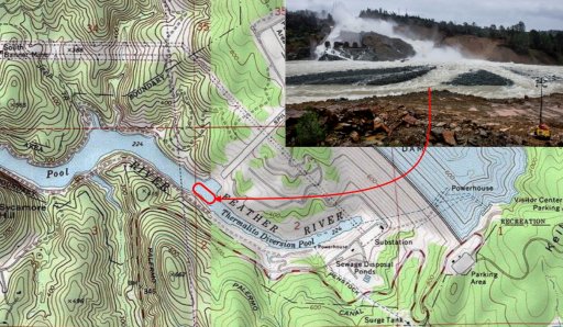
Oroville Dam USGS Topo Map.jpg
 
Last edited:
Can the Main spillway be repaired ? Can it be repaired before it starts raining next year.

What about the option of building a second main spillway. So the first one can be repaired over a few years.

You're assuming that the spillway is needed every year, but it isn't always needed. Also, once the power plant is running again that can be used to encourage the level to drop to about half-full. They can run the dam in ways to minimize the reservoir storage instead of maximizing it, such as by stopping pumping of water back behind the dam for power generation.

 
>>You're assuming that the spillway is needed every year...

Yes I am... Because no one know what will happen next year... IMO the emergency spillway is rubbish.

Clearly the Main spillway must be shut off to repair it... to many unknowns after that.

I guess one plan would be.... Fix the power plant, keep the lake as low as possible. Begin repairs on the main spillway even if it takes over a year. If there is mega rain next year and the lake goes to 900 feet, open the main spillway and destroy much of your work.

I mean what else can they do ?

Eddie
 
How about you wait a week or two (when we can actually see what damage there is), and see what they are saying. I see no point in speculating wildly at this point.

Agreed. The damaged area is going to be examined, as will the edge of the remaining spillway. We also don't know the preferences of professional engineers for the new design. Maybe there's a requirement that the new spillway rest on bedrock, and that will drastically change the situation over what we've found from the original designs and lab work.
 
How about you wait a week or two (when we can actually see what damage there is), and see what they are saying. I see no point in speculating wildly at this point.

Can't quote it exactly, but I do remember in one of the earlier press conferences, one of the speakers (wish I could remember who!) said that the spillway couldn't possibly be completely fixed next year and maybe not even the year after that. I apologize for not having a link to the source, if someone can find the exact quote please let me know. Meanwhile I will try my darnest to find it...
 
You're assuming that the spillway is needed every year, but it isn't always needed.

In fact, the spillway wasn't used at all in 2009 according to the last full annual report at the source link.
upload_2017-2-22_16-3-10.png
Source: www.water.ca.gov/swp/operationscontrol/annual.cfm

I did some curiosity research on the Palermo Canal and believe it to be a cold water source for the fishery. Not enough volume to matter in this discussion.

This chart also shows flows through the power plant capable of offsetting most inflows through the year. Also note that the lake surface only barely broke over El.800 once.
 
Can't quote it exactly, but I do remember in one of the earlier press conferences, one of the speakers (wish I could remember who!) said that the spillway couldn't possibly be completely fixed next year and maybe not even the year after that. I apologize for not having a link to the source, if someone can find the exact quote please let me know. Meanwhile I will try my darnest to find it...
unfortunately we need specifics (more recent updates, not to further confuse readers) for ex: i see on Feb 11th noon conference Coyle said [working before Oct 15th], but that must have been before the emergency spillway flow over started. and having to restart/increase the flow on the main spillway.

So let's try to keep updates on information more current.
 
Last edited:
>>
Clearly the Main spillway must be shut off to repair it... to many unknowns after that.
Eddie

Based on what I have seen, most of the main spillway is not worth salvaging - too much seepage and too many cracks. As you point out it's risky to rebuild the main, as they really only have from May to January to do it. Other months are at risks of spills They could spend money on an overlay for the upper part, but will that last 50 years?

A new alignment north may be the best option so they can build year-round without risk of losing their work. That way they have a damaged, but working spillway. With a little innovative design, they might keep the radial gate structure and flow to the new chute when complete. Moving that much water in a different direction is a challenge, though.

Build a new, smaller auxiliary spillway control structure, or even a proper weir wall, in place of the flawed emergency spillway along the parking lot ...

Build the control structure at the end of the existing 900' weir - where the parking lot part of spillway starts. As there is rock/dirt embankment on reservoir side the outlet structure could be excavated from down slope side - build the control structure - then excavate intake channel ... with minimal work the existing emergency spillway could remain operational if needed

We know the down slope hillside is most all bedrock just below the surface. Use the existing channel below the parking lot road ... clean up the natural ravine and add a little hardening where necessary.

A North route is a possibility from the culdesac area at that end of parking lot ....
 
Friendly reminder: This isn't the "design a new spillway" thread. It's a current event thread for discussing what's actually going on now at Oroville.
 
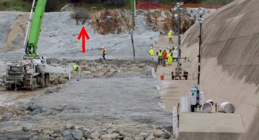
The tree is toast:
20170222-225602-oj67t.jpg

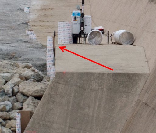
Interesting all the half concrete forms they have there, like they are going to install a fence. Seem oddly spaced. Maybe drain related.
 
Interesting all the half concrete forms they have there, like they are going to install a fence. Seem oddly spaced. Maybe drain related.

Instrumentation? Subsurface sensor?
EDIT
Cancelled edit.

INSTRUMENTATION 23-02-2017 2-25-54 AM.jpg

As for the tree being toast, I think it is just migrating out of Dodge as fast as it can go:

TREE 23-02-2017 2-17-42 AM.jpg
 
Last edited:
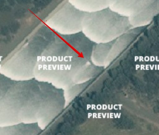
Does anyone know the date of this image? This is apparently a product preview provided by a satellite image service. Can the original poster provide the date upon which the satellite performed the actual capture?

RAW FAILURE ZONE 20170218-074913-hhytq.jpg

Did a Google search on site:metabunk.org and found lots of interesting images but not this one. Lots more images returned on a general web search but still not this one. I'm pretty sure it was collected from MB.
 
Last edited:
Yes, I have been following that thread and in the lower section, I would agree with you. However, in the upper section it appears that the fence has poles more frequently (perhaps due to the risk of junk coming through the gates, or idiots trying to go over it?).
Here is an annotated version of the picture you posted showing the workers on the spillway (from
http://pixel-ca-dwr.photoshelter.co...Ip7IY/KG-oroville-damage-13013-02-20-2017-jpg originally) I made a box the same height as the workers (for boxes 1 and 2) and the same height as the fence (box 3) then I copied the boxes and rotated them to match the angle of the fence posts:
Spillway fence.png
The distance is not going to match due to the perspective, but if the fence is 3-4' tall and the workers are 5'-6' tall, the posts are not 10' apart in THIS section (it looks like it may change spacing at the R10 mark).
If you look at the other pictures from today, they show the same spacing.
Here is one that you included that shows the close spacing of the posts hear the gates:


Here is another from the Pixle site showing a closeup of the fence where it appears that you can see the spacing change (I put a red line at each post):
Source: http://cdn.c.photoshelter.com/img-g...flwefms2040ed20170224o4_MQ.LCnWXvT5Y/fit=1040
KG_oroville_damage-13075_02_20_2017.jpg


Aaron Z
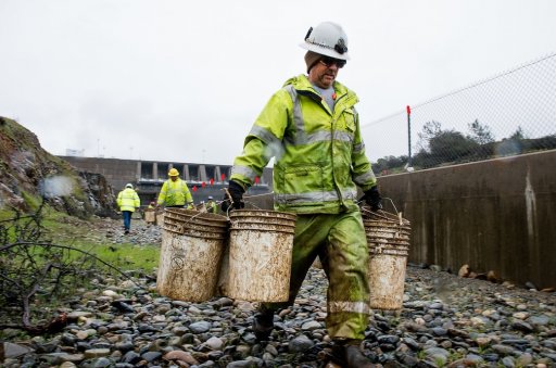
Hi - Long time listerner - first time caller. Great site. Not sure if someone has already commented but I am fairly certain that the brown stuff is bentonite that is being mixed, put into buckets and seemingly being tamped down along the side of the spillway. I'm a geotechnical engineer and have designed small dams using similar bentonite pellets to form anti seep collars around outlet pipes. Basically swelling clay used to limit groundwater seepages. Strange that they are mixing it by hand like this and in such small buckets - even with my relatively small dams we mixed it more efficiently and in larger volumes.

It does raise the question of concerns about ingress of groundwater from the surrounding country especially the way it is being tamped in a narrow line - possibly a cut off trench?

Cheers
Eugene
 
Does anyone know the date of this image? This is apparently a product preview provided by a satellite image service. Can the original poster provide the date upon which the satellite performed the actual capture?

RAW FAILURE ZONE 20170218-074913-hhytq.jpg

Did a Google search on site:metabunk.org and found lots of interesting images but not this one. Lots more images returned on a general web search but still not this one. I'm pretty sure it was collected from MB.

The original post with that image was by Moderator Mick and is now on the Pre-Failure Images thread as post #26. The date of the image given there is 2 May 2016.
https://www.metabunk.org/pre-failure-oroville-dam-spillway-historical-images.t8410/#post-201250

The image site it came from is Terraserver and it can be found here: https://www.terraserver.com/view?utf8=✓&search_text=39.53986, -121.49537&searchLat=39.53976&searchLng=-121.49537&lat=&lng=&bbox=&center=
 
Last edited by a moderator:
Basically swelling clay used to limit groundwater seepages.
Hi. Pouring trenches with bentonite is a perfect practice to fight seepage and deep erosion. Can you however, explain how such narrow application of bentonite over the gravel will work?
 
The original post with that image was by Moderator Mick and is now on the Pre-Failure Images thread as post #26. The date of the image given there is 2 May 2016.

Thanks Boilermaker.

MIck - I just checked the date at the Terraserver site. The date given is confirmed as May 2nd 2016.

According to my timeline the first flow after a few years of drought was March 24th 2016:

MARCH 14 2016 LAKE OROVILLE RISING
https://mng-chico.smugmug.com/Lake-Oroville-Rising-3-14-2016/i-BVJdxc2
https://mng-chico.smugmug.com/Lake-Oroville-Rising-3-14-2016/i-TpG7JpR/A
MARCH 24 2016 SPILLWAY FLOWS FOR THE FIRST TIME IN A LONG TIME
https://mng-chico.smugmug.com/Oroville-Week-of-3-28-2016/i-3WMFDpc

Good quality image at www.chicoer.com 3/25/2016 shows drains operating (spillway, upstream lookers right drains). I could not extract exif data so used date in the URL. Flow was ~6kcfs on this date, and 0 during daylight hours on previous few days.

---
The DWR flow data contains data from water through the power house and also the by-pass. My understanding is that all of this volume is reported as a single draw down. Was there regular usage of the FCS spillway after May 2nd 2016? Or was this a single usage?
 
Status
Not open for further replies.
Back
Top