Are Lynch's Horizon Calculations correct?

DarkStar

Active Member
Spherical Trig Help Needed :)

I had posted a blog post about viewing the horizon from high-altitude, roughly based on Lynch's paper 'Visually discerning the curvature of the Earth' -- or so I thought.

One problem with such calculations is we're talking about small quantities and since I had created my calculator in GeoGebra I was pretty confident that the values I were getting were correct so I didn't really test them as carefully as I should have.

A friendly person did a little 'peer-review' and started asking me some questions and I had to agree, something wasn't right. Now, I freely admit that my calculator is just an approximation (to avoid one bit of spherical conversion that doesn't change the end result much) but it should be accurate enough for realistic altitudes (35,000' and maybe a balloon at 120,000'); so I'm not worried about that part so much.

But it turns out I had definitely misunderstood Lynch's intended geometry and after a bit of work I *THINK* I see where we disagree.

So now I'm here looking for additional input and review. Meanwhile, I have flagged that section of my post as under review.

So you can review Lynch's paper and then compare my blog post and see what you think.

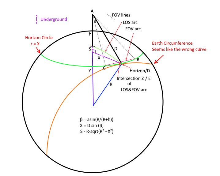
I created the diagram below to aid in discussing my model. Please distinguish if you are talking about this 'Darkstar' model or Lynch paper when referring to geometric labels. In this version I made both LOS arc and FOV arc spherical. That's really the only difference with my GeoGebra model (and the way things are labelled a bit).

What I *think* the Lynch model is doing (in terms of this diagram) is pushing points B & C out to the Orange "Earth Circumference" curve, and his X is a function of the FOV (chord C->B) and his S is the sagitta of THAT arc of R=Earth Radius (so rotate that whole YXR triangle and attach to midpoint of B&C and then other end at B (or C doesn't matter).

What makes me suspect this is that in Lynch's paper his S & R are in terms of Earth Circumference -- but his X calculation isn't given so it took some work with another person to sort this out in my mind (wasn't obvious to me).

So the question is -- IF (and that's a big IF) my understand of Lynch is correct -- isn't that the wrong geometry to be using? You cannot see the Earth circumference along that slice EXCEPT at Horizon/D (well, in practice you can't see that either due to atmosphere but we're talking ideal model here).


For calculation purposes let's stick to Lynch's example:

h = 35000' (observation height ~6.6288 mi)
R = 3959 mi (approx Earth Radius)
h.FOV ~ 62.7
v.FOV ~ 47.1

In my model I get a very small angle (0.041°) because you can see that the last ~33 miles (which is approximately where points B & C cut across) is almost completely coincident with the views line of sight. The angle between viewer->Z and viewer->horizon here is that 0.041° so that's how much my model says that horizon would be 'stick up' over that B->C chord from our viewpoint.

We both agree on the first few calculations:

(1) first I solve big right triangle for D and β: (R+h)² = R² + D²
(2) D = sqrt(2*R*h + h²) = ~229.196 mi
(3) β = asin(R/(R+h)) ~ 86.687°
(4) α = acos(R/(R+h)) ~ 3.313°

Here we Diverge... for Darkstar model:

X = (D*sin(β)) = 228.81295 mi -- this is the radius of my horizon circle (just a little shorter than D)

And we take the chord B->C, calculate the sagitta of that, and then we take the angular delta along that line of sight -- which is very small because that distance is all very tilted along our line of sight.


Working Lynch backwards he gets ~0.51° -- so that implies...

2*atan(S/D/2) = 0.51° (angular size of S at distance D)
S ~ 2.037 mi (height of sagitta)

S = R - sqrt(R² - X²)
X ~ 126.993 mi

I'm still working on how to calculate his value for X given h.FOV -- I have an idea and it's close to D*tan(h.FOV/2) but I have to adjust for S.


Thoughts?


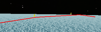
Here is what my side view looks like however and viewer height and the circle of the Earth here are trivially correct so that's an accurate view as far as that goes. You can see how sharp that angle becomes as you get closer to the horizon point. Z here is 33.4 *MILES* (β Curvature Distance) from the horizon. Even if I have everything else wrong human beings are NOT seeing most of that 'distance to the horizon' as more than a tiny smear and an anthill at Z would completely block it :)

'Circle Diameter' here is that bottom red line. Distance to Base is viewer total distance to the bottom red line (viewer->X), Height is viewer->Y

upload_2016-8-27_18-13-53.png
 
I'm still working on how to calculate his value for X given h.FOV -- I have an idea and it's close to D*tan(h.FOV/2) but I have to adjust for S.

Why would X vary based on h.FOV? FOV does not change the distance to the horizon.
(Edit: different X in the two diagrams)
 
Last edited:
Your diagram is a little confusing to me, you talk about S being the sagitta of B->C, but it seems on your diagram (and from the math) that it's the larger sagitta of the entire horizon circle. i.e. the distance from the surface of the sphere below the viewer down to the plane of the horizon circle.
 
Your diagram is a little confusing to me, you talk about S being the sagitta of B->C, but it seems on your diagram (and from the math) that it's the larger sagitta of the entire horizon circle. i.e. the distance from the surface of the sphere below the viewer down to the plane of the horizon circle.

Yeah it's confusing - bear with me. I spent 2 days studying it. Lynch's Sagitta is arc of BC - not mine - if that helps.

First of all remember my diagram is what I think the geometry should be, not what Lynch appears to be using.

I don't think it lines up with Lynch at all because we get different answers: 0.51 vs 0.04 degrees.

Lynch talks about FOV in the paper and obviously FOV has a huge impact on how much of a 'hump' you would expect to see:


But where does Lynch take into account FOV if not in X? I also say this because Lynch is using R = earth radius in his calculations and never uses the circle of the horizon that I can see.

So it seems that Lynch is assuming you see the edge as being the circumference of the Earth as you might if it was extremely far away, instead of a circle that forms your horizon and is tilted.

So to get from my diagram to Lynch (I believe) you have to push B & C out to the orange circumference and somehow figure out X as being related to FOV and from that you get ~2 miles high and he takes the angular size of that as 0.51 degrees.

In my calculation I slice the earth almost perpendicular to Lynch to get your horizon circle and then B->C forms a Chord on that much smaller circle, and then I take the height of that arc and measure that many miles back *along the sphere of the Earth* and take the angle between those two spherical points - because the sphere of the earth makes that portion be very tilted to our point of view I get a very small angle.


So we need to figure out how Lynch intended his X to be calculated and I gave the number by reversing the formula so we know about what it should be. I could easily be wrong about his geometry but didn't see how else it could work.

I'll try to make a diagram for it in the meantime.

It's very hard to discuss in words, I struggled with it for 2 days before I got it.

Try this in the meantime -- take 'this arc' below and imagine Lynch's diagram being placed inside THAT circle (which is earth radius).

image.jpeg

image.jpeg

Now the point where XYS meet is that 'limb' of the Earth - or where your horizon hit the edge of your photo. That's why I think Lynch's X is related to FOV. Which is ALMOST D*atan(h.FOV/2) but not quite (it would be a little bit closer than D, where BC crosses.
 
So here is what I think the Lynch geometry is based on -- hopefully this makes more sense at least in terms of what I'm talking about. I don't *KNOW* that this is the right geometry but this is the only way it makes sense to me.

I'm sorry the perspective is way off - I'm not an artist :) The idea is that the Lynch diagram is a plane that cuts through the center of the Earth at the horizon point.

[ignore Horizon Circle r=X, it's not X in this case, forgot to erase that]

HorizonGeometryLynch.png

Remember that R is Earth Radius -- how else do you put that diagram into the picture and make R=Earth Radius fit?

This is *clearly* a different S that I'm computing and if I'm correct that this is the Lynch geometry I think he's doing the wrong calculation because B & C should really fall on the green 'Horizon Circle'.

Now if I just take X = D*tan(h.FOV/2) [this is just 1/2 the angular diameter formula) I get *pretty* close - but I want to know exactly what we should be getting and it's just not clear to me yet.

X = D*tan(h.FOV/2) ~ 139.6273 mi
S ~ 2.5 mi
S/D ~ 0.615°
 
Last edited:
Just to clarify, does this essentially show what you are trying to calculate? The sagitta, expressed as degrees in the photo?
20160829-100728-wmywq.jpg
 
Just to clarify, does this essentially show what you are trying to calculate? The sagitta, expressed as degrees in the photo?

Yes with the caution here that we are viewing the Horizon Circle at a steep angle so that Sagitta is very slanted to the viewer (and that lenses are not uniform - a lot of what you see in that specific image is lens barrel) -- if you looked directly down at this you would have (in miles for the 35,000' view):

upload_2016-8-29_14-3-13.png

And my point is that points B & C should be on this green 'Horizon Circle' of Radius [D*sin(β) ~ 228.81 mi @ 35,000'] -- not on a curve with Radius = Earth Radius -- the Earth Radius curve that intersects the point of Horizon Peak is HIDDEN around the curvature from us.

And when you 'rotate' to the side view with Z at ~33.4 miles from horizon you get a VERY VERY small angle for that bit of the horizon between Z/E and the horizon peak.

upload_2016-8-29_14-6-33.png


At 250 miles up, 62.7 degrees, I get sagitta = 196 miles:

upload_2016-8-29_14-10-35.png

But increase that to 90 degree FOV and I get one full degree.

upload_2016-8-29_14-11-35.png


Increase FOV to 120 degrees:

upload_2016-8-29_14-12-36.png


Or at 179 degree FOV the Sagitta is huge and the increases rapidly to 63 degrees as you widen that FOV.

upload_2016-8-29_14-13-37.png

I would say my geometry is the correct one and the angle is usually even smaller than Lynch suggested because of this tilt at the horizon point.

Where (it seems to me) that Lynch is essentially projecting it onto that plane at the horizon and taking the height of that arc as the angular size.
 
Why would X vary based on h.FOV? FOV does not change the distance to the horizon.
(Edit: different X in the two diagrams)

Well, I *think* it's different -- I'm not positive but I don't see how else it works in Lynch's system but I'm open to other interpretations. :)
 
(tl;dr - did calculations like a 3D -> 2D projection, got same answer as Lynch)


If our primary reference for measuring things is comprised of photos, then just describing things in terms of angular size only makes sense in a spherical projection, but most regular camera lenses are rectilinear. You can't simply measure angular size from a photo. We really want to know how many pixels the drop will be, or perhaps as percentage of the height of the image.

I find it easier to think in terms of 3D coordinate geometry and how that's projected into 2D. Let's say that up/down is Y, left/right (relative to the camera) is X and the camera is looking along the Z axis. So any point (X,Y,Z) can be projected to 2D as [X/Z,Y/Z] to give the coordinates of the point in the photo (where the center of the photo is (0,0))

We do the calculations for the actual plane of the horizon circle. Which (in the Darkstar model) is of radius X, and I'm going to use Z, and the camera is S + h above the center, which I'll call H for here. .

Now with the camera level (parallel to the horizon plane, not pointed at the horizon), the horizon will be a bit below the center of the image, in 3D the coordinates the center horizon will be [x,y,z] = [0,S+h,Z] (where Z is the radius of the horizon circle). So in 2D it will be [0,H/Z] (y axis is positive down here, so H/Z is below [0,0] in the center of the image)

Now the points at the side are mirrored so lets just take the one on the right. It has the same y coordinate (H) as the center of the horizon, but different x and z. For a FOV of (a) degrees, x is Z*sin(a/2) and z is Z*cos(a/2), so the coordinates are [x,y,z] = [Z*sin(a/2), (S+h),Z*cos(a/2)], which gives a 2D projection of [Z*sin(a/2)/(Z*cos(a/2)), H/(Z*cos(a/2))]

Recap: in the projected image with horizontal FOV = a degrees, we have
  • The center high point of the horizon at [0,H/Z]
  • The side low point at [sin(a/2)/(cos(a/2)), H/(Z*cos(a/2))]
So the vertical (y) difference in 2D of these is H/(Z*cos(a/2))-H/Z (or H/Z*(1/cos(a/2)-1)

In what units? The are basically X/Y ratios, not actual values. But we have the horizontal FOV, and we know that it goes to sin(a/2)/cos(a/2) on one side, so the full width is 2*sin(a/2)/cos(a/2), so as a portion of the width of the 2D image it's

H/Z*(1/cos(a/2)-1)/(2*sin(a/2)/cos(a/2))

So in pixels, you would just multiply that by the width of the image in pixel, or (if you like) the horizontal FOV in degrees.

Plugging in Darkstar's numbers from the OP for sanity check.

h = 35000' (observation height ~6.6288 mi)
R = 3959 mi (approx Earth Radius)
h.FOV ~ 62.7
v.FOV ~ 47.1

Horizon distance D = 229.196 miles.
β = asin(R/(R+h)) ~ 86.687°
X (Mick's Z) = (D*sin(β)) = 228.81295 mi


H (h+S) = (D*cos(β)) = 13.24536

a = h.FOV, 62.7, so a/2 = 31.35 degrees, 0.54716072 radians.

As a portion of the width, the drop is
H/Z*(1/cos(a/2)-1)/(2*sin(a/2)/cos(a/2))
13.24536/228.81295*(1/cos(0.54716072)-1)/(2*sin(0.54716072)/(cos(0.54716072)) = 0.00812206

In "degrees", *62.7 = 0.509


Which is the the same as Lynch, which suggests what he is doing is correct.


I found an error in SHCC (only affecting horizons when you move your house to 35,000 ft), but I think it might be ok now. 31 spots total, for 60deg. HFOV

What is SHCC?


Google Earth Pro (atmosphere off)
35k' at h.FOV 62.7 (see attached kml file if that works)
I tried to make the window square (I was at 980x997)
I got an 'arc' about ~8 pixels high -- which suggests: (62.7/997)*8 ~ 0.503°

BUT (before we declare Lynch's victory here)

Viewer is at exactly 0° / 0° - looking directly North

I also create two 'pins'.

HorizonMarker at 3.005549° (~229 miles), is just on the horizon
SagittaMarker at 1.75° (~8 pixels down) (~120 miles away from viewer)
Which gives an off horizon sagitta of ~109 miles (229-120)

How does Google Earth get 109 miles? I only get ~33.4 miles - for 109 miles I need a 117° FOV which gives me about 0.73° angle between those two points. If I move SagittaMarker out to where I think it should be ~2.5° (~195.6 miles away) it's WAY out on the Horizon.

I used: http://williams.best.vwh.net/gccalc.htm (sm, WGS84) [the middle red line is a path I marked from North Pole to Equator along 0°, the horizontal line I marked to show where the chord crosses.] Here are my two pins.

upload_2016-8-29_16-35-45.png


However, I'm not sure that Google Earth is doing a very good job rendering here either, that's the same N/S red line in Google Earth itself but viewing from a bit to the side (it's like Sandor's laser :)

upload_2016-8-29_16-46-24.png

So this could be fairly useless.

And the question remains -- how do you calculate to get ~0.5° here?
 

Attachments

  • FOV-TEST 62.7 at 35k.kml
    697 bytes · Views: 851
  • upload_2016-8-29_16-47-14.png
    upload_2016-8-29_16-47-14.png
    40.2 KB · Views: 463
My H and Z can be expressed in terms of R and h, via D
EPSON001.JPG

Intermediate forms
Z=(R*sqrt((R+h)^2-R^2))/(R+h))
H=(((R+h)^2-R^2)/(R+h))


Which all simplifies to H/Z = SQRT(h*(h+2*R))/R
And (1/cos(a/2)-1)/(2*sin(a/2)/cos(a/2)) simplifies as tan(a/4)/2 (where a = h.fov)
So the whole thing simplifies as SQRT(h*(h+2*R))/R*tan(a/4)/2 (* a, if you want approx angles)

https://www.wolframalpha.com/input/?i=solve+SQRT(h*(h+2*R))/R*tan(a/4)/2*a,+h=6.6288,R=3959,a=(62.7+degrees)
20160829-151356-8edp4.jpg

(and SQRT(h*(h+2*R) is just D, so you can have super simple D/R*tan(a/4)/2, but you still need to calculate D)
 
Last edited:
Lynch's graph:
20160829-163007-pt64o.jpg

A graph with my equations:

20160829-163044-4mheq.jpg
(Made with OSX Grapher, file attached)
 

Attachments

  • Curve of the Horizon.gcx.zip
    780.4 KB · Views: 663
Last edited:
Lynche's graph (red) is similar to mine (black), but not the same.
20160829-163721-cemah.jpg

I suspect this is due to the difference between rectilinear projection and angular measurements, but I'm not entirely sure.

However it would seem like his calculations are basically correct, even if it's unclear exactly what he's doing in the paper.

EDIT, or maybe not - consider the distance to the horizon and the radius of the horizon circle are quite similar, so if he's dividing by D instead of Z, then that also might account for the error difference
 
Last edited:
Yes, this is what I hoping to get to :)

Quick reference:
X-axis=left(-)/right(+)
Y-axis=up(-)/down(+)
Z-axis=looking along Z axis(+)

Z=horizon radius
H=observer height (S+h)
camera = [0,0,0] - looking at Z+

We do the calculations for the actual plane of the horizon circle. Which (in the Darkstar model) is of radius X, and I'm going to use Z, and the camera is S + h above the center, which I'll call H for here. .

Ok, so [0,0,0] is the 'camera' correct? And I assume in 2D 0,0 is the center of our "view"?

Now with the camera level (parallel to the horizon plane, not pointed at the horizon), the horizon will be a bit below the center of the image, in 3D the coordinates the center horizon will be [x,y,z] = [0,S+h,Z] (where Z is the radius of the horizon circle). So in 2D it will be [0,H/Z] (y axis is positive down here, so H/Z is below [0,0] in the center of the image)

[0,H,Z] -> [0/Z, H/Z] -> [0, H/Z]

Ok.

Now the points at the side are mirrored so lets just take the one on the right. It has the same y coordinate (H) as the center of the horizon, but different x and z. For a FOV of (a) degrees, x is Z*sin(a/2) and z is Z*cos(a/2), so the coordinates are [x,y,z] = [Z*sin(a/2), (S+h),Z*cos(a/2)],

Ok, I think maybe this is where I am off.

I think I'm taking the angle from

[0,H,Z] to [0,0,0] to [0,H-EarthHeight,Z cos(a/2)]

EarthHeight here is about 1.8 miles so that's significant and while useful information I think that is not the right answer to the question.

upload_2016-8-29_18-27-56.png

But point B is really in the Horizon Plane, not EarthHeight above it.

If I lower that point so my angles are:

[0,H,Z], [0,0,0], [0,H,Z cos(a/2)]

I then get 0.567° - which oddly seems to match your H/Z*(1/cos(a/2)-1

So I'll need to review this a little more in depth to understand this bit.

So the vertical (y) difference in 2D of these is H/(Z*cos(a/2))-H/Z (or H/Z*(1/cos(a/2)-1)

since tan(x) = sin(x)/cos(x) that makes your conversion - which, if you think about it, converts your ratio to 'actual size' - just like it would in an angular diameter calculation :)

H/Z*(1/cos(a/2)-1 / (2*tan(a/2))


Quick sanity check, our Horizon 'Dip' angle should be:

H/(Z*cos(a/2)) / (2*tan(a/2)) = 3.188°

MetabunkCurve says: 3.313°

any idea why we're off here? My calc matches Metabunk:

upload_2016-8-29_19-42-45.png

As a portion of the width, the drop is
H/Z*(1/cos(a/2)-1)/(2*sin(a/2)/cos(a/2))
13.24536/228.81295*(1/cos(0.54716072)-1)/(2*sin(0.54716072)/(cos(0.54716072)) = 0.00812206

When/how does vertical FOV come into play? Bit confused by that point.


I gotta run for now. REALLY appreciate this -- this is definitely adding clarity to the calculation.


Which is the the same as Lynch, which suggests what he is doing is correct.

Well, you are at ~0.4653 degrees but his is mark is just over 0.5 degree.

And I'm a little bit too wide of an angle now.

Do we have any idea how Lynch would be computing his X value then? I think we need to figure this out so we can compare at various altitudes to make sure we stay in agreement and aren't just 'close' because we're near 1/2 a degree here.

upload_2016-8-29_19-20-58.png
 
Let's try it out 400 miles up. I used a transparent photo with a red frame. When you add the photo to GE it tells you the FOV (50° horizontal)
20160829-180427-dhlj2.jpg

I then measured the width and height of the frame, and the vertical curve drop of the horizon.

SQRT(h*(h+2*R))/R*tan(a/4)/2 gives you the drop as a portion of the width of the image, so we have to multiply by 1348 to get it in pixels.

Solving for h=400,
https://www.wolframalpha.com/input/?i=solve+SQRT(h*(h+2*R))/R*tan(a/4)/2*1348,+h=400,R=3959,a=(50+degrees)

20160829-180754-4jpql.jpg

68.84, which is essentially the same as the measured 69.
 
Last edited:
When/how does vertical FOV come into play? Bit confused by that point.

It doesn't really. The horizontal FOV defines the left and right sides of the image, and hence defines where the lowest point of the horizon is.

The vertical FOV just defines the aspect ratio of the resultant image, assuming you use square 2D coordinates (like you would).

The equation results in the "drop" as a portion of the width of the image. Like if it returned 0.05, and the width of the image was 1000 pixels, then the drop would be 50 pixels. This just assumes that things are rendered square, like they are in a camera and in Google Earth and in real life.
 
Last edited:
Quick sanity check, our Horizon 'Dip' angle should be:

H/(Z*cos(a/2)) / (2*tan(a/2)) = 3.188°

MetabunkCurve says: 3.313°


any idea why we're off here? My calc matches Metabunk:


The dip should be atan(H/Z) which is atan(13.24536/228.81295) = 3.313

So I'm not sure where you are getting your equation.
 
EDIT, or maybe not - consider the distance to the horizon and the radius of the horizon circle are quite similar, so if he's dividing by D instead of Z, then that also might account for the error difference

Yeah, he said he was, I assumed he was looking 'down' at the horizon point.
 
The dip should be atan(H/Z) which is atan(13.24536/228.81295) = 3.313

So I'm not sure where you are getting your equation.

Ok, got it. Just trying to wrap my head around these transforms and used the wrong coordinates. I'm ready to write some code now.

So I guess the only question left is the disconnect in the two curve figures.

Once we do that you could build this into the curve calculator :)
 
Ok, got it. Just trying to wrap my head around these transforms and used the wrong coordinates. I'm ready to write some code now.

So I guess the only question left is the disconnect in the two curve figures.

Once we do that you could build this into the curve calculator :)
If only pilots laid bricks with a level we would know if the earth was round.
 
If we want to go directly to the angular distance of the drop then it's the difference between the "dip" to the horizon, and the dip to the midpoint of the chord (i.e. the bottom of the sagitta, on the horizon plane)
Horizon dip is atan(Z/H), chord dip is atan(Z*cos(a/2)/H) so the angle subtended at the camera is
(atan(Z/H)-atan(Z*cos(a/2)/H))

For our 35,000 feet case:
solve 180/PI*(atan(Z/H)-atan(Z*cos(a/2)/H)), Z=228.81295, H=13.24536, a=(62.7 degrees)

Result = 0.5648

Which is quite different to 0.509 (about 11% bigger)\

with Z and H in terms of R and h it's a bit more complicated, and I think there must be a simplification, but my trig is rusty.
atan((R*sqrt((R+h)^2-R^2))/(R+h))/(((R+h)^2-R^2)/(R+h)))-atan((R*sqrt((R+h)^2-R^2))/(R+h))*cos(a/2)/(((R+h)^2-R^2)/(R+h)))
 
Last edited:
I've updated my calculator (will work on the blog entry next). The only geometry change I made is to move my point Z down to the horizon circle plane instead of being on the surface of the Earth. I also made it so Z moves automatically with B and I cleaned up the labels and text display. I added in FOV scaled "H/Z" and "H/D" angles for now (details below).

If we want to go directly to the angular distance of the drop then it's the difference between the "dip" to the horizon, and the dip to the midpoint of the chord (i.e. the bottom of the sagitta, on the horizon plane)
Horizon dip is atan(Z/H), chord dip is atan(Z*cos(a/2)/H) so the angle subtended at the camera is
(atan(Z/H)-atan(Z*cos(a/2)/H))

For our 35,000 feet case:
solve 180/PI*(atan(Z/H)-atan(Z*cos(a/2)/H)), Z=228.81295, H=13.24536, a=(62.7 degrees)

Result = 0.5648

I'm trying to wrap my head around this part and what 0.509° means (vs 0.5648) in terms of the geometry or projection?


Here is what I have now:

upload_2016-8-30_15-2-29.png

The labels above are for the points which I will use only to identify line segments. Point D is tangent to our "Spherical Earth Approximation" so forms right angle from the origin of our "Spherical Earth Approximation" to O (same as before of course, just documenting for posterity).

Here is the raw math so far:

FOV=62.7° ~ 1.094321 rad (aka 'a' in Mick's formulas)
R=3959 mi radius of our Spherical Earth Approximation
h=35000/5280 height of observer (~6.6288 mi)
β=asin(R / (R + h)) angle for XOD (~1.5129685436 rad)
D=sqrt(h (h + 2R)) distance for OD (~229.1957 mi)
Z=(D R) / (h + R) distance for XD (~228.8126 mi), aka D*sin(β)
S=R - sqrt(R² - Z²) distance for XY (~6.6177 mi)
H=D cos(β) distance for OX (~13.2464 mi), aka S+h
sagitta = Z versin(FOV/2) = Z(1-cos(FOV/2)) (~ 34.4 mi)

"H/Z Angle" = H / Z (1 / cos(FOV / 2) - 1) / (2tan(FOV / 2)) * FOV
"H/D Angle" = H / D (1 / cos(FOV / 2) - 1) / (2tan(FOV / 2)) * FOV

Horizon dip =atan(Z/H)
Chord dip = atan(Z*cos(FOV/2)/H)
"Horizon Sagitta Angle (θ)" = (Horizon dip - Chord dip) = (~0.5648°)

If you wanna try it out:

https://www.geogebra.org/m/RxvhcBk4

Should I add vertical image pixels and calculate the number of pixels? :)
 
Last edited:
I'm trying to wrap my head around this part and what 0.509° means (vs 0.5648) in terms of the geometry or projection?

I think it's related to the fact that my method returns a fraction of the width of the image. This is NOT the same as an angle, but I think it's far more useful. You can convert this accurately to pixels, but you cannot convert it to degrees. At least not in a straightforward manner. My calculation of the "Angle" was simply multiplying the fraction (0.00812206) by the FOV (62.7). But the ratio between distance across the image and angles varies with the distance from the center of the screen.

Consider this setup (viewed from above):
20160830-132014-uvk87.jpg
There's a yardstick against the wall (36 inches long). There's a camera pointed at the center of the yardstick (18"). On the right I've marked two sections A and B, both are 9" long. I've also marked the angles made by the sections at the camera. Notice that the angle closer to the center (b) is larger than the angle on the outside (a). This is more apparent if we have a wider field of view:20160830-132403-47eu1.jpg

However the two sections on the photo take up the same number of pixels. So that's why you can't just multiply the fraction by the FOV to get the angle. The further from the center you go, a single pixel has a reduced angle
So how do you convert? Well let's say the image has a width of 1.0 (to match the fraction we got earlier). So the distance from the center of the image (k) is -0.5 to 0.5. If the FOV is a°, then the FOV similarly goes from -a/2 to +a/2, then the angle for a distance k is atan(2*k*tan(a/2)).

(i.e. it's a fraction of the tangent of the angle, not a fraction of the angle)

If we apply that simply to the fraction, we get:
https://www.wolframalpha.com/input/?i=solve+180/pi*atan(2*0.00812206*tan(a/2)),+a=(62.7+degrees)

= 0.567

This is not exactly correct as the angle is a bit below the center of the screen, but it's close as the relative error is small near the center and the edge.
 
I think it's related to the fact that my method returns a fraction of the width of the image. This is NOT the same as an angle, but I think it's far more useful. You can convert this accurately to pixels, but you cannot convert it to degrees. At least not in a straightforward manner.

...

This is not exactly correct as the angle is a bit below the center of the screen, but it's close as the relative error is small near the center and the edge.

Ok -- so is it fair to say the 'true' angle is:

"Horizon Sagitta Angle (θ)" = (Horizon dip - Chord dip) = (~0.5648°)

But that when evaluating a photograph we must also take into account the properties of that lens and how it maps the actual FOV into the pixels?
 
Ok -- so is it fair to say the 'true' angle is:

"Horizon Sagitta Angle (θ)" = (Horizon dip - Chord dip) = (~0.5648°)

Yes.

But that when evaluating a photograph we must also take into account the properties of that lens and how it maps the actual FOV into the pixels?

Technically yes. However in practice this will only be a significant factor for non-rectilinear lens. If your lens maps all lines as straight lines, then you are fine. If it does not then that's an entirely different kettle of fish.

If you are being particularly precise, then even good quality lenses have some distortion and you might want to correct that. Photoshop has a lens database with correction information. This is a before and after of the close shot:
lens-correcton-example-metabunk.gif
This works in that it makes the spacing linear. However here it's also reducing the FOV a little. You could figure all that out, but it's probably overkill, particularly for measurements like this one which are close to the centerline.

The above is for a 10mm lens, 99° FOV, which is pretty wide. However if you centered and leveled the horizon you can still probably ignore the lens correction.
 
Last edited:
Yes.


Technically yes. However in practice this will only be a significant factor for non-rectilinear lens. If your lens maps all lines as straight lines, then you are fine. If it does not then that's an entirely different kettle of fish.

If you are being particularly precise, then even good quality lenses have some distortion and you might want to correct that. Photoshop has a lens database with correction information. This is a before and after of the close shot:
lens-correcton-example-metabunk.gif
This works in that it makes the spacing linear. However here it's also reducing the FOV a little. You could figure all that out, but it's probably overkill, particularly for measurements like this one which are close to the centerline.

I used a simple variable lense correction for SHCC depending on the zoom. I simply tweak it to fit the horizon and landmarks. That is why the horizon is curved!
 
Ok, trying to use this on an image. I got this frame dead center on the horizon near the max altitude so I went with 100k

From right around this point (I have a frame-by-frame plugin):
Source: https://youtu.be/9dfVtaZbuIQ?t=12170


upload_2016-8-30_19-11-13.png

upload_2016-8-30_19-13-7.png

I'm guessing some of that 38 pixels is just thick horizon.

But I'm still off a good bit even using H/Z calculation. Can you double check me?

It's a Hero 3 White Edition 1080p = 'Medium' FOV.

I found this: https://gopro.com/support/articles/hero3-field-of-view-fov-information

But that's for Black edition so I just hoped it was the same 94.4 deg FOV but may not be.
 
But I'm still off a good bit even using H/Z calculation. Can you double check me?

It's a fraction of the horizontal span, not the vertical. Use 1920 pixels as the multiplier.

Pixels are square, so it works in both directions.
 
I got this frame dead center on the horizon

I think this example might not work though, as it's not a rectilinear lens, you can see the horizon curving up and down as it moves around. How did you get it "dead center"?
 
I think this example might not work though, as it's not a rectilinear lens, you can see the horizon curving up and down as it moves around. How did you get it "dead center"?

Yeah... Was hoping center of lens distortion would be small enough to get close.

I get 41 pixels using 1920 pixels. That's pretty close. Since points below center bend 'up' we're off in the right direction.

I was thinking to capture curve at a few points above and below center and map the distortion with a curvilinear grid superimposed on the images.

I have a chrome plugin that does frame-by-frame in YouTube and I set up paint.net with a center spot layer and photo layer below that then just eyeballed it, alt-printscreen, paste into paint.net, move a few frames, until I got one centered.
 
I was thinking to capture curve at a few points above and below center and map the distortion with a curvilinear grid superimposed on the images.

It's possible there might be a filter that converts to rectilinear with a lens database similar to Photoshop, but for video.
 
Today's bit of fun... is tilting the camera 'down' by atan(H/Z) (fortunately we just have to rotate one axis)

The rotational matrix for x-axis rotation is:

⎡x⎤ ⎡ 1 0 0 ⎤
⎢y⎥ ⎢ 0 cos -sin ⎥
⎣z⎦ ⎣ 0 sin cos ⎦


Given an angle u the equations to transform x, y, and z coordinates are:

x' = x
y' = y*cos(u) - z*sin(u)
z' = y*sin(u) + z*cos(u)

Since we are 'looking down' we need to rotate 'up' so our angle will be positive and equal to Horizon Dip to bring P right into the center of our frame at [0,0].

Our point P starts at [0, H, Z] and we rotate by u=atan(H/Z)

x' = 0
y' = H*cos(atan(H/Z) - Z*sin(atan(H/Z)) = 0
z' = H*sin(atan(H/Z)) + Z*cos(atan(H/Z)) = D

P' = [0, 0, D] -> [0, 0]

That was easy because the rotation exactly cancels out the previous H/Z slope to that point as intended.

Next up is the hard one - doing point B, then taking Δy


I know this is going to make VERY little difference in practice but I want to nail this down.


I might have to cry if it simplifies to H/D :)
 
Last edited:
Ok... not H/D I think... but need to triple check this and simplify it.

h=(35000/5280), R=3959, a=62.7°, p=2048
H=(((h*R)/(h+R))+h)
D=sqrt(h*(h+2*R))
Z=(((sqrt(h*(h+2*R)))*R)/(h+R))
u=atan(H/Z)

B = [Z sin(a/2), H, Z cos(a/2)]
And we rotate:
x' = Z sin(a/2)
y' = H*cos(u) - (Z cos(a/2))*sin(u)
z' = H*sin(u) + (Z cos(a/2))*cos(u)
B' = [Z sin(a/2), H*cos(u) - (Z cos(a/2))*sin(u), H*sin(u) + (Z cos(a/2))*cos(u)]

and project into 2D:

B" = [(Z sin(a/2)) / (H*sin(u) + (Z cos(a/2))*cos(u)), (H*cos(u) - (Z cos(a/2))*sin(u)) / (H*sin(u) + (Z cos(a/2))*cos(u))]

Find Δy between P" and B" - we get a break here because P".y is zero

Δy = (H*cos(u) - (Z cos(a/2))*sin(u)) / (H*sin(u) + (Z cos(a/2))*cos(u))

and convert to the ratio of our field of view and multiply by the number of pixels in our horizontal field of view.

Δy / (2*tan(a/2)) * p

So

(H*cos(u) - (Z cos(a/2))*sin(u)) / (H*sin(u) + (Z cos(a/2))*cos(u))) / (2*tan(a/2)) * p = 16.5704100433

this is longer than wolfram|alpha likes to deal with so I used Desmos:

https://www.desmos.com/calculator/q5vi3oh1oq

Cell #39 is this calculation

Thoughts?
 
Seems like you are calculating the screen pixels of the sagitta dip when the camera is centered on the horizon? aka (the fraction of the width of the screen the sagitta would cover if turned horizontal) * (the width of the screen in pixels)

We know the angle subtended at the camera (s) , so the simplest thing to do is take that angle, and convert it to the fraction k assuming it's measured from the center

From above,
s = atan(2*k*tan(a/2)) (which we used as an inexact way of converting fraction to angle, as it's not on the centerline)

k = tan(s)/(2*tan(a/2)) (which gives us an exact fraction measured from the centerline)

s = saggita dip angle - horizon dip angle
s = atan(Z*cos(a/2)/H) - atan(Z/H)

k = tan(atan(Z*cos(a/2)/H) - atan(Z/H))/(2*tan(a/2))
(or with H on top, depending on which angle you prefer to consider.)
k = tan(atan(H/(Z*cos(a/2))) - atan(H/Z))/(2*tan(a/2))

Plugging in your H&Z numbers from the desmos calculator:
solve 2048*tan(atan(H/(Z*cos(a/2))) - atan(H/Z))/(2*tan(a/2)), H=13.2464953385, Z=228.812616816,a=(62.7 degrees)
https://www.wolframalpha.com/input/?i=solve+2048*tan(atan(H/(Z*cos(a/2)))+-+atan(H/Z))/(2*tan(a/2)),+H=13.2464953385,+Z=228.812616816,a=(62.7+degrees)

Result: 16.57
 
Last edited:
Simple diagram. The angle s is easy to calculate from H and Z, so we just take that angle and assume it's from the horizon, so convert it to a tangent fraction20160901-171209-4si23.jpg
 
Back
Top