Apologies for unclear post - will clarify here
re: erosion site in Figure 182 of gateway elevation cited at
https://www.metabunk.org/oroville-dam-spillway-failure.t8381/reply?quote=200941 (to avoid contravening the no click rule, here's an excerpt
View attachment 24807
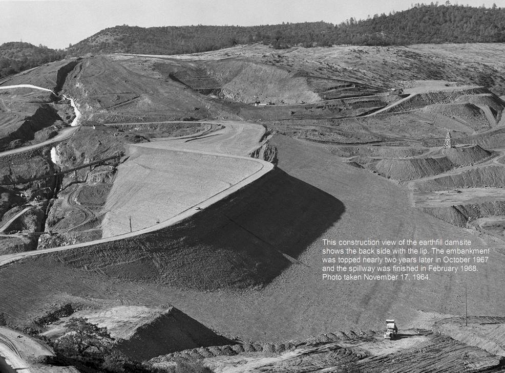
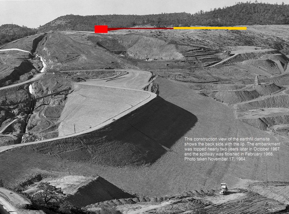
The emergency spillway (at left above) isn't "all the way to the top of the ridge" as Scott describes.
Labelled "groin" the bedrock is only 840' in elevation at the base of ogee weir (≠ TOP elevation at 901 ft).
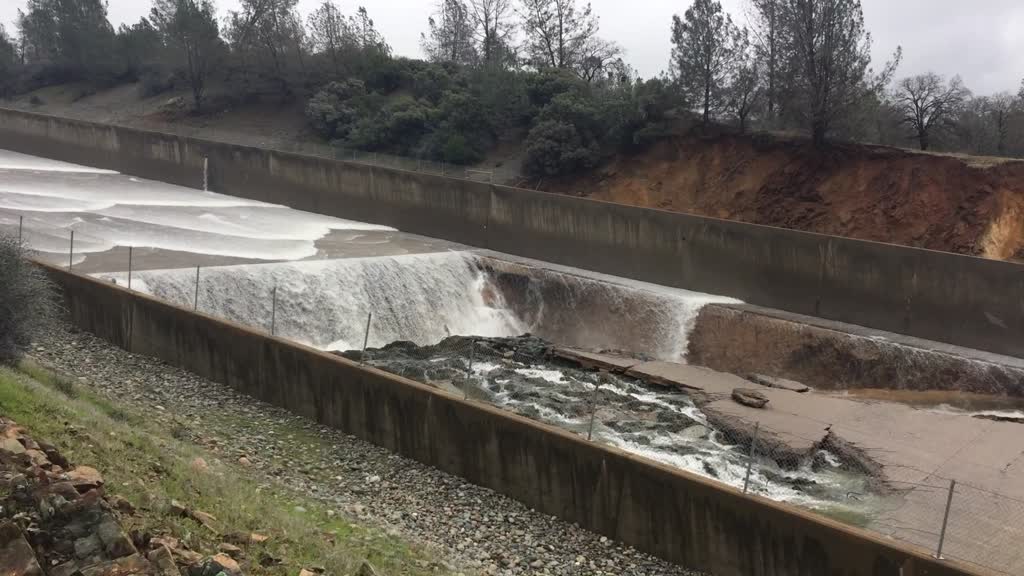
The gap in the approach wall (at top center above) shown in CDRW photo
I posted earlier (deleted for
Not meeting Posting Guidelines sorry for the inconvenience) demonstrates turbulence but not erosion. Since the wall is only shown in plan (elevation not shown from rear) I can only guess how tall that section of the escarpment cut is - certainly beneath the spillway road at 870' but perhaps higher than the ogee weir at 840'
View attachment 24808
The right-side of shute labelled "berm" and "cut escarpment" in red above present a risk to the permeable surfaces at 872' rising to 888' when passing water in excess of 901' (ie flood overspill levels across the spillway).
Only 100 ft separate the abuttment of the dam berm rising to 922' indicated behind dashed line labelled "Contract limit" in red (schematic above not photo above). Moisture penetration under pressure could infiltrate slowly via seepage into the dam itself.

")