After the aircraft impact, gravity loads that were previously carried by severed columns were redistributed
to other columns. The north wall lost about 7 percent of its loads after impact. Most of the load was
transferred by the hat truss, and the rest was redistributed to the adjacent exterior walls by spandrels. Due
to the impact damage and the tilting of the building to the north after impact, the south wall also lost
gravity load, and about 7 percent was transferred by the hat truss. As a result, the east and west walls and
the core gained the redistributed loads through the hat truss.
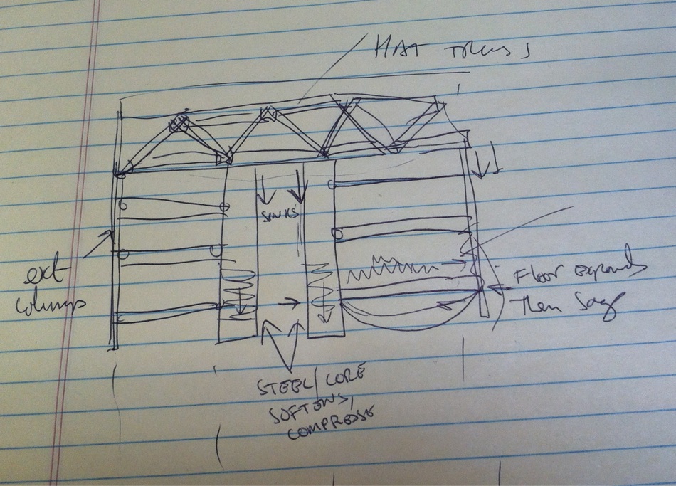
Structural steel and concrete expand when heated. In the early stages of the fire, temperatures of
structural members in the core rose, and the resulting thermal expansion of the core columns was greater
than the thermal expansion of the (cooler) exterior walls. The floors also thermally expanded in the early
stages of the fires. About 20 min after the aircraft impact, the difference in the thermal expansion
between the core and exterior walls, which was resisted by the hat truss, caused the core columns' loads
to increase. As floor temperatures increased, the floors sagged and began to pull inward on the exterior
wall. As the fires continued to heat areas of the core that were without insulation, the columns weakened
and shortened and began to transfer their loads to the exterior walls through the hat truss until the south
wall started to bow inward due to the inward pull of the sagging floors. At about 100 min, approximately
20 percent of the core loads had been transferred by the hat truss to the exterior walls due to weakening of
the core, the loads on the north and south walls had each increased by about 10 percent, and those on the
east and west walls had about a 25 percent increase. The increased loads on the east and west walls were
due to their relatively higher stiffness compared to the impact damaged north wall and bowed south walls.
The inward bowing of the south wall caused failure of exterior column splices and spandrels, and these
columns became unstable. The instability spread horizontally across the entire south face. The south
wall, now unable to bear its gravity loads, redistributed these loads to the thermally weakened core
through the hat truss and to the east and west walls through the spandrels. The building section above the
impact zone began tilting to the south as the columns on the east and west walls rapidly became unable to
carry the increased loads. This further increased the gravity loads on the core columns. The gravity loads
could no longer be redistributed, nor could the remaining core and perimeter columns support the gravity
loads from the floors above. Once the upper building section began to move downwards, the weakened
structure in the impact and fire zone was not able to absorb the tremendous energy of the falling building
section and global collapse ensued.