Hypothesis - Rotation of Gimbal not caused by lens glare.

Daniel F

Member
Hi there,

This is by no means done with arrogance and claiming to be the correct interpretation. Just think there is enough evidence to warrant the hypothesis and a discussion. Apologies if this is similar in some ways to other threads but felt hypothesis and attached evidence can stand alone.

Hypothesis - The rotation on screen is due to the object rotating, or some other hitherto unknown artefact, rather than a consequence of rotating glare caused by lens rotation.
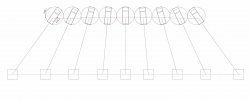
Exhibit A.

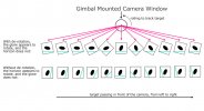
Tracking motion of the ATFLIR. A constant rotation is needed to keep track. If glare was the rotating artefact then it would be consistent throughout. This image shows that the lens, bound to two axis, must follow this motion to keep the object in view.
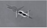
1622810993824.jpeg


Exhibit B.

Artefacts in sky are rotating with the F18 rather than object.
Very difficult to track the light artefacts in sky. I’ve marked one such area on images with green line. Easier to see in motion, but this shows rotation of object in relation to artefacts in sky and rotation of F18 in relation to artefacts in sky. Though neither are perfect, the tracking is more in line with banking of F18 rather the object in sight. Particularly the final large rotation that the object does is not followed by artefacts in sky.
1622811032464.jpeg

Watch this video by Mick West where the video scrubs back and forth at critical moment. If you block out the object, the rotating artefacts in sky follow rotation of F18. Whereas if you block out the central bars denoting the level of F18, the object seems to continue rotating at a higher rate than said artefacts.


Source: https://youtu.be/4Btns91W5J8


Also the bumps along the way are due to turbulence, culminating in a larger bump at the end, possibly due to changing wind pressure over F18 as it rotates. This happens to coincide with final rotation of object but I postulate that the slight bump in its position is merely due to the turbulence and the camera being zoomed in rather than the camera suddenly rotating.
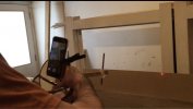
 
Okay I will post this again here

The outer gimbal does not generally have to rotate to track an object side to side.


Source: https://youtu.be/AcsAZTKRv5E?t=39

This video doesn’t show that the gimbal doesn’t need to rotate. I’ve done some physical experiments and any gimbal must rotate without question if following that path. If an object was perfectly level with the camera and moved all the way across without deviation of its vertical position , only then would a gimbal not need to rotate. Then there would be know sudden lens glare rotation either. If an object is above or below, or a combination of the two through any given track, by virtue of its locked 2 axis, it must rotate, in this example just like exhibit A.
 
What I would like to see is an objective debate with the ufo fans and the scientific skeptics. The skeptic community takes so much of their time debunking these grainy, videos without much data involved. If the ufo fans out there want to see aliens then let them. The so called news interviews the same players in their community without so much as a skeptical response. They do it for views & clicks and the ufo hustlers do it for money. We skeptics do it for free.
 
The f18 is also banking which compounds the issue, I think.

Micks videos are great, but they are generally pared down for the more casual observer, you seem to want to discuss details, have you read through the full Gimbal thread? There is a lot of posts that talk about the patents and technical diagrams for the ATFLIR, there are mirrors/heliostats inside the pod that help with tracking and correction, some small tracks can happen without rotating the external gimbal system at all etc.
 
I have read through the posts. I agree Micks videos are fantastic. Thats what brought me here. The gimbal rotation glare theory is also fantastic. I’m in no way trying to trash one theory or another and I’m also not Raytheon atflir technician - I’m a bespoke joiner :) not quite the same field, I think you’ll agree ! I’m just interested in the mechanics of things and working through problems that’s all. This gimbal video is held up as the poster boy for UFO nuts so warrants as deep as analysis as can be managed. It’s really difficult to explain, but I have a stumbling block with the glare theory. We are tracking an object miles away with a zoomed in camera. The object travels a significant distance across. I don’t think that any combination of internal mirrors can do that work. The front pod/ball/gimbal has to be facing the object to keep in view. Its facing a very small spot in the sky, miles away. Once a target drifted past a certain point, no amount of mirror rotation could keep track. I’m just hypothesising that this is a real consideration regarding lens flare. Again, no disrespect intended at all. Its just bothering me and I was wondering if someone could explain some other reason. As Mick says in the video- the gimbal must do a major correction at the centre point as it passes by which in turn cause the glare to rotate.
Here is another drawing, if you look closely you can see the red line marks the travel of the 2nd axis. It’s very small. It’s all mainly rotation. That’s just my understanding of it and am happy to be corrected.
 

Attachments

  • 9855F251-CE0D-410B-A6AC-C2D70CD3BFFF.jpeg
    9855F251-CE0D-410B-A6AC-C2D70CD3BFFF.jpeg
    65.3 KB · Views: 308
You've got this strange fixed idea that the cylinder rotation is needed to track left-right. That would hardly help. It's far simpler to do it with ball rotation.

Start like this.

2021-06-04_07-50-41.jpg
 
Micks videos are great, but they are generally pared down for the more casual observer, you seem to want to discuss details, have you read through the full Gimbal thread? There is a lot of posts that talk about the patents and technical diagrams for the ATFLIR, there are mirrors/heliostats inside the pod that help with tracking and correction, some small tracks can happen without rotating the external gimbal system at all etc.
Thanks. I have been saying this couple of times. There is an active DE-ROTATOR in the ATFLIR to make the image upright at all times (gimbal tracking makes the frame rotate). I am now too lazy to dig up the patent design drawings though.
 
You've got this strange fixed idea that the cylinder rotation is needed to track left-right. That would hardly help. It's far simpler to do it with ball rotation.

Start like this.

2021-06-04_07-50-41.jpg
:) Admittedly I am full of strange ideas !
I had thought of that starting point obviously but -
Are the internal mirrors really able to see and track a target 54 degrees left from this position and track it right across ? This presumption is different to your workshop video.
If that’s correct, I don’t understand why the pod would suddenly rotate at the centre. It would just remain in that horizontal position as the target continued would it not ?
The other point I was making is that the f18 is in a 40 degree bank or thereabouts and swinging round on the target. That’s a sweep of miles and miles in the sky. Although the screen is reading a level 2 deg down throughout, that’s in relation to the jet but in relation to the camera it is also a large change in vertical position, as well as horizontal.
I think that the pod itself would always be pointed at the tracked target and mirrors would be working in unison for finer adjustment at distance. I would imagine targets could be lost easily if the pod stayed centrally static whilst tracking such a wide target. Any deviation whilst at its limits and the target is gone.
Is the target tracked via the smaller window next to main lens ? If it is, then I would think, again, that the pod must track constantly or maybe it uses the same set of mirrors.
Finally, if the mirrors internally could keep track of the target through that large path, it would be a lot of motion relative to the front lens?
So in summary, the main theory is that it is not the gimbal pod tracking the target as in your workshop video, but it is internal mirrors doing all the movement . These mirrors, despite moving independently to the front lens, would not cause any glare rotation across that wide path, but when it gets to centre, the entire pod must rotate for some reason and it is the front lens moving first, independent of the internal mirrors which cause the glare to rotate ?
 
Also, Mick, I do mean the ball rotates and not the cylinder. That is what is happening in the last pic I posted.The ball must rotate around. The lens is on the ball, hence the lens is constantly rotating.
 
Thanks. I have been saying this couple of times. There is an active DE-ROTATOR in the ATFLIR to make the image upright at all times (gimbal tracking makes the frame rotate). I am now too lazy to dig up the patent design drawings though.
I understand that the derotating device constantly corrects the image. My point is that, given the coordinates that the gimbal (stuck to two axis ) is tracking, it must constantly rotate. I apologise sincerely if I’m missing something blatantly obvious. Here is a sophisticated re-enactment of the tracking :)
 

Attachments

  • FullSizeRender.mov
    8.5 MB
Are the internal mirrors really able to see and track a target 54 degrees left from this position and track it right across ? This presumption is different to your workshop video.
No, but it does not need a cylinder rotation, which it what rotates the glare, until it need to adjust for the 0° traversal.
 
I’m sorry if we are talking past each other somewhat. It’s difficult to describe. I fear I’m flogging a dead horse here.
I’m talking about the front ball that the lens is housed in. Which I drew in images above.
There are 2 axis on a gimbal.
The middle section with lens can pivot. This would not cause glare. Or the ball can rotate which includes the middle section, therefore rotating the lens as well. This would cause a rotating glare once the image is de rotated. The front ball is detached from the receiving camera with a de rotation device in between to rectify the image.

Now if would could hold this Raytheon ball in front of our chest and wanted the camera to look at something 2 deg down and 54 deg to our left. The only possible combination of movements we can do to allow us to look at it is the following.

-Hold the ball either side (3 oclock and 9 o’clock) with the pivot section; such that it can pivot up or down in front of us on a vertical plane.
-Pivot the lense slightly down ( no rotation ).
-Then rotate the whole ball clockwise till we find the target ( rotating the lens in process ) Our hands would travel from say 3 and 9 o’clock to around 11 and 5.

Now to track this imaginary target across our field of view at a constant 2 deg below we must

-Ever so slightly and steadily pivot the lens back up it’s axis ( no rotation ) and
at same time
-rotate the ball steadily counter clockwise ( rotating the lens in process ) until target was in front.
more rotation than pivot.

Then to keep tracking it off to the right we would

-start to pivot the lens in the opposite direction back down ( no rotation ) and at same time we would
-keep rotating the entire ball counterclockwise as before ( therefore rotating lens ).

Forget what any internal mirrors may or may not do. If we just move the gimbal as we know they work, as we can see it move on Raytheon company adverts, restricted on those two axis, as you showed in your video demonstration, then it must follow that path described. There is no other combination of pivot/ rotation that can achieve what we want.
We cannot hold the gimbal with its pivot horizontally and just pivot all the way across without rotating the ball as the target is below us.
Then if you extrapolate this out to an object miles to our left and 2 degrees down and put us in a 40 deg bank then we certainly wouldn’t be able to just keep the lens pivoting left to right.
 
I can’t get the videos to work so will just post a few pictures of the process and then shut up.
Using my highly sophisticated devices including -
wife’s vanity mirror ( it can pivot on one axis and its base rotates on another
laser
pencil
as I said, highly sophisticated...
You can see I must pivot down and rotate the face that laser is mounted
Then rotate counter clockwise all the way. Slightly raising the face with laser.
hope this visually explains what I’m trying to say, that the lens must rotate nice and easy all the way. Because the target is below, I can’t just swing the laser from left to right without rotation it would just be above.
 

Attachments

  • 392DD7A7-431F-4894-BF6D-47CEE5E35DA3.jpeg
    392DD7A7-431F-4894-BF6D-47CEE5E35DA3.jpeg
    107.6 KB · Views: 815
  • 0A8F2E40-3B34-4478-9BA4-F0048B3DAE65.jpeg
    0A8F2E40-3B34-4478-9BA4-F0048B3DAE65.jpeg
    102.6 KB · Views: 247
  • 740446AD-05FD-41E7-8CB2-AE4041CEBE6E.jpeg
    740446AD-05FD-41E7-8CB2-AE4041CEBE6E.jpeg
    100.3 KB · Views: 783
  • E4E62DB7-E5D6-4267-B2A8-C2EC4C587B3E.jpeg
    E4E62DB7-E5D6-4267-B2A8-C2EC4C587B3E.jpeg
    101.4 KB · Views: 225
  • 4AA9A6CD-D705-4B9C-BE8C-D6CA21691FE0.jpeg
    4AA9A6CD-D705-4B9C-BE8C-D6CA21691FE0.jpeg
    121.9 KB · Views: 245
Last edited:
Apologies it’s not the best quality but this was a video which I can’t upload.
 

Attachments

  • 3DCEB22E-EF16-471A-9447-4B58A4BE89A1.jpeg
    3DCEB22E-EF16-471A-9447-4B58A4BE89A1.jpeg
    70.6 KB · Views: 540
  • 8BC69D8F-1032-49E8-8AFB-F350014B71C3.jpeg
    8BC69D8F-1032-49E8-8AFB-F350014B71C3.jpeg
    70.9 KB · Views: 240
  • 82B8F77A-591B-44F9-AF98-32720EE6D94C.jpeg
    82B8F77A-591B-44F9-AF98-32720EE6D94C.jpeg
    67.3 KB · Views: 262
Note the effect above of the shallow angle. The jig I'm using is more that 2*, so the effect in reality would be even more pronounced.
 
Mick, I’ve just had another idea which would possibly work regarding your glare rotation hypothesis.
As I keep waffling on about; I’m not convinced the pod would need a sudden rotation at centre when tracking an object across. I think it’s a constant relatively consistent rotation. But there could be a scenario where a sudden rotation is required that pilots maybe surprised to see. It needs the bank angle, speed of f18 and the object to all conspire against the atflir.
Could it be that the 2 deg below is actually a rather deceptive bit of data. If the f18 is banking 20+ deg and the object is steadily swinging around. Maybe the object remains relatively ‘above‘ the camera throughout. The steady change of left to right maybe equates to more of a steady up to down for camera , and gets the pod into a gimbal lock scenario as it is in a poor position when the sudden combination of f18 levelling and object reaching centre. see attached image
What about the scenario in this picture ?
BA4B9CFB-9C3D-4C64-8219-D83EB1A98123.jpeg
 
This would mean all the initial tracking is done with the pivot up and down of lens ( no rotation ) all the way up until the gimbal lock at which point we get rotation suddenly to correct.
 
Yes I did. My point is that the rotation ( perpendicular screw ) must rotate consistently from the start and wouldn’t give us this sudden move as in gimbal footage. Disregard my last thought and diagram above though. Thinking again, it wouldn’t change things.
Whether the angle is very shallow or quite steep. The screw would rotate smoothly throughout. Obviously, visibly more pronounced at centre when the screw passes vertical but, as a rotating action, it is quite slow and steady. The more shallow the angle the more total roll required. The deeper the angle then the screw would just progressively not need to start as for around. The aspect that would change it the most would be the speed at which we swing around or if the object was very close. We would have to whip it around. Even then, though the rotation would be visible from the start and not begin at centre,
 
Even then, though the rotation would be visible from the start and not begin at centre,
No, the patents are quite explicit that such rotations are to be minimized.

Consider the case at 0° horizontal. just going left to right. You could do that with zero rotations of the long axis.
 
Last edited:
My understanding is that the front end is in constant motion maintaining line of sight and that internal mirrors provide fine tracking and a safety bracket of around +-3 degrees to avoid gimbal lock. That the mirrors effectively create an extra axis to minimise any motion towards gimbal lock but could not, would not be used exclusively to follow an object all the way from 54 deg left to past centre and 2 deg down ? My head hurts !
 
No, the patents are quite explicit that such rotations are to be minimized.

Consider the case at 0° horizontal. just going left to right. You cloud do that with zero rotations of the long axis.
Yes you are right, you could track right across at 0 deg with zero rotation and just pitch of lens. Also, regarding f18 pitched 20 on side, and reading that target is 2 deg below. I think that’s just 2 deg below the horizontal plane of f18 ? The atflir is having to do something different than that ? Is it more like it’s starting a few deg above camera ?
 
The closer the target passes to the pod's forward direction, the more abrupt the rotation will seem:
 

Attachments

  • Gimbal.jpg
    Gimbal.jpg
    167.5 KB · Views: 286
The closer the target passes to the pod's forward direction, the more abrupt the rotation will seem:
Good image. The key words here are non-linear angular motion. It is kind of a cosine effect. I think Daniel F forgets that the image needs de-rotation.
 
The closer the target passes to the pod's forward direction, the more abrupt the rotation will seem:
Thanks saucerpilot. I apologise if I’m being a total dummy here but I still can’t get it. :) A lost cause !
Mick‘s ( fantastic ) hypothesis is that the rotation of unit at centre point is a sudden correction, which would make the glare rotate only at the centre line. My issue remains that the unit must rotate and it’s a steady degrees of rotation of lens from start to finish. The screw in Micks video gives an idea but also accentuates what seems a sudden rotation but if you follow it like hands on a clock, it is a somewhat continuous travel around the clock.Therefore a glare on lens would rotates from the get go and not how we observe in gimbal footage.
I wish my video would work on here. I attached a laser to a device with the 2 axis that a gimbal is restricted. I then followed a target across.
- It’s a ( somewhat counter intuitively to me ) steady rotation of the laser throughout -
Minimal pitching of laser as it rotates does the work of keeping on line. This is the only way a gimbal restricted to 2 axis can follow such a path.
So if we observed an image through this imaginary lens; a glare would rotate throughout. The image would be constantly de rotated .
 
IamGoddard found a perfect example of what I would expect to see. A constant rotation.
 

Attachments

  • D1B4BF04-975D-4305-A276-0FECCEB72CD5.jpeg
    D1B4BF04-975D-4305-A276-0FECCEB72CD5.jpeg
    211.6 KB · Views: 269
Back
Top