The pre-collapse inward bowing of WTC2

Not saying that heating of (mostly the inward side of) the perimeter columns was a major contributor, just that even 250C heating would contribute yet another slight allowance for bowing. Perhaps by linear expansion on the inward side more than by loss of strength.
If I were to guess what the greatest contribution was I would say load redistribution. Sagging trusses simply offered a mechansim by which bowing was preferentially inward over several floors where sagging trusses were.
Sure. Just watch for "chicken and egg" with the load redistribution aspect. (What started it for that part of the structure?) And, no, I haven't a clue where the bits interacted in either time or space. There is a limit to "engineer's gut feelings" esp this time of year despite the alcoholic assistance. (Cabernet/Merlot à la Aussie style "Chateaux Cardboard".) BUT I do know they:
1) Interacted; AND
2) It was complicated to understand. ;)
 
It's sensible to assume that all moved, moving, displaced, distorted, broken components changed the load paths from the static to something dynamic which led to a state where the loads exceeded the limits / capacity of components, nodes , elements. We can assume this because it was a process which evolved over time. Knowing with any specificity is probably a fools errand. But it would be a stretch to say.. X bolt's failure was THE straw that broke the camel's back.... it was A straw.
 
It's sensible to assume that all moved, moving, displaced, distorted, broken components changed the load paths from the static to something dynamic which led to a state where the loads exceeded the limits / capacity of components, nodes , elements. We can assume this because it was a process which evolved over time. Knowing with any specificity is probably a fools errand. But it would be a stretch to say.. X bolt's failure was THE straw that broke the camel's back.... it was A straw.
:
1) Interacted; AND
2) It was complicated to understand. ;)
Yes.
I am involved, on another forum, in arguing about the relative probability of advanced alien life versus the existence of ESP. There are knowns and unknowns, same as here.

As Jeffrey points out load paths DID change. We also know that inward bowing of a long expanse of perimeter columns occurred. Of course the behaviour of steel under load is also well known. Thus it is quite probable that the changes in load distribution contributed in significant fashion, to the inward bowing. Of course it could, in theory also have been huge chains anchored to several core columns and using automated hydraulic machinery, drew the perimeter inward in a deliberate operation thus confounding the efforts of 911 CTs who purport that the towers were taken down by explosives.;)
 
... Of course it could, in theory also have been huge chains anchored to several core columns and using automated hydraulic machinery, drew the perimeter inward in a deliberate operation thus confounding the efforts of 911 CTs who purport that the towers were taken down by explosives.;)
Vérinage.
 
Vérinage.
Well yea... and do you think if a verinage of the twin towers were to be done they would "pull" the building down by attaching one or two of those trusses to the facade and "pulling".

I've seen rigging done and the size of the shackles used... you can even see the size of the shackles used to hoist up those very facade panels that bowed inward.,.. They are HUGE. Obviously they don't use the smallest shackle that would do the job... and maybe use the largest one for convenience purpose...but what could have been heavier that those facade panels? Again they weighed different amounts depending on the height of the building they were placed...got it. But again... the pull in of any significance by the truss and the connecting bolts doesn't seem to be a kick off of the bowing.
 
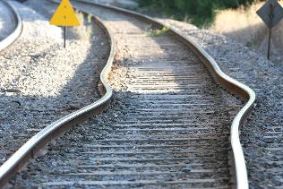
you don't need a lot of heat to get steel expanding.

This is what a hot spell 30oC plus weather and direct sunlight can do to railway tracks

So I don't find it hard to accept that the wtc fires could cause enough heat expansion to warp the buildings steel structure to cause distortion.
 
you don't need a lot of heat to get steel expanding.

This is what a hot spell 30oC plus weather and direct sunlight can do to railway tracks

So I don't find it hard to accept that the wtc fires could cause enough heat expansion to warp the buildings steel structure to cause distortion.

Of course this is true... but if the expanded steel was a relatively flimsy could of bar trusses restrained by robust steel sections... the expansion is going to appear as sagging!... And not pushing the robust columns or as others assert... pulling them together (IB)
 
Of course this is true... but if the expanded steel was a relatively flimsy could of bar trusses restrained by robust steel sections... the expansion is going to appear as sagging!... And not pushing the robust columns or as others assert... pulling them together (IB)

You could probably do the math on that one.
 
You could probably do the math on that one.
Usmani did the math on a 2D model and found the flimsy joists would push the robust exterior panels out 15 mm. Usmani mentions spandrels and the vertical load distribution they effect once, but I can't assess if and how their action wrt lateral forces is covered by the model.

But in any case, I take Usmani's math over Jeffrey Orling's gut feeling as my null hypotesis. Usmani is certainly "wrong" to some degree, but his math result may serve as a first approxomation to what expanding joists may do to the facade.


Hold on... everyone is claiming they pull IN and I am claiming (guessing) they don't do boo but act as an asymmetrical load which influences the bowing to be inward. If they expand they BOW not push... just a guess.
 
I think that these "9/11" discussions have been done to death (no irony intended).

The "exact" mechanisms of the reasons for those buildings to collapse? As caught on film? This is rather pointless. (Except for structural engineers, perhaps, who wish to design better buildings in the future). Meaning? There are engineering aspects for MANY structures that must be "earthquake resilient", for instance...(to name a few)...
 
Hold on... everyone is claiming they pull IN and I am claiming (guessing) they don't do boo but act as an asymmetrical load which influences the bowing to be inward. If they expand they BOW not push... just a guess.
I don't comprehend the distinction you make between "pull IN" and "an asymmetrical load which influences the bowing to be inward" - the later sounds like a complicated way of saying "pull IN"

And you are still falling for a couple of conflations:
1) Push out and pull in are two distinct stages. STAGE 1 Push out before the joist is hot enough to sag. It still operates as a thermally expanding strut. STAGE 2 Pull in due catenary sag AFTER the joist is hot enough to sag. THEN

2) Stage two has two overlaying aspects viz:
(a) The joist is still getting longer due to thermal expansion of its length; BUT
(b) The sagging including the extra length forms a catenary which exerts pull in.

Thermal expansion of length and catenary pull in are not mutually exclusive.
 
I think that these "9/11" discussions have been done to death (no irony intended).
Depends on your range of interest. If you are not interested - then you are not interested. Doesn't satisfy J Sander Orling who is interested. (And usually trusts my judgement - we are friends :rolleyes: )

Explaining for those who are interested is still valid - and "interested" is not IMO limited to designers of future buildings.
 
But in any case, I take Usmani's math over Jeffrey Orling's gut feeling as my null hypotesis.
I'll take my own gut feeling backed by clear reasoning before either of them. ;)

Usmani is certainly "wrong" to some degree, but his math result may serve as a first approxomation to what expanding joists may do to the facade.
True enough but its very rough. Szamboti, Newtons Bit, enik and a couple of others have published similar findings. They use FEA - I could do it on my slide rule (my generation of engineering - I don't have access to FEA software.) (And to answer the next question - just and very slowly. :oops: )
 
I don't comprehend the distinction you make between "pull IN" and "an asymmetrical load which influences the bowing to be inward" - the later sounds like a complicated way of saying "pull IN"

And you are still falling for a couple of conflations:
1) Push out and pull in are two distinct stages. STAGE 1 Push out before the joist is hot enough to sag. It still operates as a thermally expanding strut. STAGE 2 Pull in due catenary sag AFTER the joist is hot enough to sag. THEN

2) Stage two has two overlaying aspects viz:
(a) The joist is still getting longer due to thermal expansion of its length; BUT
(b) The sagging including the extra length forms a catenary which exerts pull in.

Thermal expansion of length and catenary pull in are not mutually exclusive.

I think the world of Ozzie...

I suppose the issue is not pull in or... is the lateral load sufficient to DISTORT the facade columns??? Certainly not very much even as an asymmetrical . load. But let's do a little thought experiment.

Attach three floors...30 feet in length to one side of the 36' high facade panel... say a 10' wide section. pin the top and the bottom of the facade so it can't move. What happens? Assuming the seats and the bolted connection perform... the 3 floors will tip down like branches with heavy snow on them ... The moment will perhaps induce some bending away from the cantilevered floor... which would appear as outward bowing.

No?
 
Hold on... everyone is claiming they pull IN and I am claiming (guessing) ...
Correct. You are guessing, Usmani is doing math.

... they don't do boo but act as an asymmetrical load which influences the bowing to be inward. If they expand they BOW not push... just a guess.
MY guess is that both push-out and bow-down happen at once: Joist heats -> expands -> goes into compression -> pushes column out -> column pushes back (Newton's 3rd) -> normal (cold, as-is live load) sag of joist increased.
 
Correct. You are guessing, Usmani is doing math.


MY guess is that both push-out and bow-down happen at once: Joist heats -> expands -> goes into compression -> pushes column out -> column pushes back (Newton's 3rd) -> normal (cold, as-is live load) sag of joist increased.

Floor systems expand... and go into compression... obviously. But only if restrained by ends.. which was the case.. and so they bow downward. SO how restrained where the ends?

I don't think the composite expanded very much. Do you? How much is the coefficient of expansion of the concrete? Would the composte rupture or would the concrete restrain the expansion... or not?

Frankly I can't answer these questions... I am not a materials scientist or engineer. The IB was over 50" I thick I read... this could not be attributed to sagging floors in a significant way.

Who is Usmani and what was his "math"?
 
Depends on your range of interest. If you are not interested -

Seriously?? ..oh I AM interested...VERY interested.

Because...I knew the co-pilot on AA77. I KNOW how to fly those airplanes. I KNOW a lot...

9/11 was "NOT" a so-called "false flag".

I ALSO lived about 2 miles away from the Pentagon....and my house SHOOK, as I was on my second floor...at the same time the upper levels OF the Pentagon fell (about 10 AM EST....)

ALSO...I drove past the Pentagon for WEEKS afterward. I have been there, physically....have seen it. I know the terrain.

I have a friend who SAW American 77 fly past his apartment window!!!

This on "Columbia Pike".....please, Google map the area, and pay close attention to Columbia Pike....
 
iirc, concrete has near the same coefficient of expansion as steel. That is , at the same temperature they expand simikarily.
Big however, the heat conductivity is vastly different and the concrete takes longer to heat up therefore the steel will expand faster.
 
(a) The joist is still getting longer due to thermal expansion of its length; BUT
(b) The sagging including the extra length forms a catenary which exerts pull in.
Would seem pretty intuitive. Truss still goes from point A to point B but now takes a longer path in between.
 
Seriously?? ..oh I AM interested...VERY interested.

Because...I knew the co-pilot on AA77. I KNOW how to fly those airplanes. I KNOW a lot...

9/11 was "NOT" a so-called "false flag".

I ALSO lived about 2 miles away from the Pentagon....and my house SHOOK, as I was on my second floor...at the same time the upper levels OF the Pentagon fell (about 10 AM EST....)

ALSO...I drove past the Pentagon for WEEKS afterward. I have been there, physically....have seen it. I know the terrain.

I have a friend who SAW American 77 fly past his apartment window!!!

This on "Columbia Pike".....please, Google map the area, and pay close attention to Columbia Pike....
We are missing each others intention. The topic of discussion current in this thread is (should be??) the technical issue of "pre-collapse inwards bowing of wtc2" My response was in that technical context which is still a matter of interest to my friend J S Orling. Hence I interpreted your comment as referring to the immediate discussion. If you are not interested in that aspect of the immediate discussion Jeffrey is. My apology that I took the context for granted - within the OP of this thread.
 
Last edited:
Who is Usmani and what was his "math"?
This is Usmani (his paper with the math, from, I think, 2002):
http://www.era.lib.ed.ac.uk/bitstream/1842/1216/1/WTCpaper.pdf
I introduced this in post #91 of this thread and first linked the paper in #98.

Floor systems expand... and go into compression... obviously. But only if restrained by ends.. which was the case.. and so they bow downward. SO how restrained where the ends?
Correct - bow downwards. And ALSO push outwards. See link above.

I don't think the composite expanded very much. Do you?
Usmani thinks so. At least if you consider 15 mm to be "much". See link above.
Now perhaps it "really" isn't 15 mm. Perhaps only 5, perhaps 45. But >0 and <<50'.
Like I said, someone with better qualification and better tools than I have at my disposal ran the math on a 2D-model that is simplified for sure (all models are), but (IMO) in the ballpark.

How much is the coefficient of expansion of the concrete? Would the composte rupture or would the concrete restrain the expansion... or not?
Details that I doubt Usmani took into consideration much.

Frankly I can't answer these questions... I am not a materials scientist or engineer. The IB was over 50" I thick I read... this could not be attributed to sagging floors in a significant way.
Nobody here is claiming that ;) The question is whether the joists and their connections are strong enough to push out and pull in the exterior walls at all (they of course are), and by how much (certainly by nowhere near to 55 inches, but also certainly by more than 0). I offer Usmani's work as one serious result that suggests an outward deflection of 15 mm, just to provide us here of an idea what order of magnitude we are talking about.
I am of course with you all that sagging trusses could not have pulled the perimeter in as far as IB went, but are a candidate for starting IB, which was then amplified by vertical loads on off-plumb columns.
 
This is Usmani (his paper with the math, from, I think, 2002):
http://www.era.lib.ed.ac.uk/bitstream/1842/1216/1/WTCpaper.pdf


Usmani thinks so. At least if you consider 15 mm to be "much". See link above.
Now perhaps it "really" isn't 15 mm. Perhaps only 5, perhaps 45. But >0 and <<50'.
Like I said, someone with better qualification and better tools than I have at my disposal ran the math on a 2D-model that is simplified for sure (all models are), but (IMO) in the ballpark.

Details that I doubt Usmani took into consideration much.

Nobody here is claiming that ;) The question is whether the joists and their connections are strong enough to push out and pull in the exterior walls at all (they of course are), and by how much (certainly by nowhere near to 55 inches, but also certainly by more than 0). I offer Usmani's work as one serious result that suggests an outward deflection of 15 mm, just to provide us here of an idea what order of magnitude we are talking about.
I am of course with you all that sagging trusses could not have pulled the perimeter in as far as IB went, but are a candidate for starting IB, which was then amplified by vertical loads on off-plumb columns.

Thank you! I don't suspect that a 15mm movement would lead to buckling of the columns. I could be wrong and often am. It seems that given the cross section of the panel this would have little effect on their ability to transfer stresses on a column/panel which was over 11,000mm tall. I don't even know if the elongation would dent or bow the column at all... as opposed to bowing downward.

We all agree that the columns had some eccentricity on the loads they carried.. mostly axial and some applied to the side at either 4 or five locations on them. Considering the magnitude of the loads the axial ones at floor 72 were far higher .. at least 10x then the side applied loads... if not more.

This discussion goes to what was the principle cause of the buckling. If it is axial overloads it means that the facade columns got handed more axial loads then they can handle... the ones that buckled. The only sensible explanation is some manner of load redistribution as no new loads were being added. Load redistribution could be the result of loss of performance of other (facade) columns... or more likely core columns... as we don't see facade columns "disappearing" or being severed in the period leading up to the bowing.

This leads me to think that the additional loads from redistribution came from the loss of core capacity. But this would mean that the load those non performing core column carried dropped... no support... or remained in place essentially their load carried by adjacent columns or the hat truss. The hat truss of course was supported by many of the columns... all the perimeter core columns and about 8 locations on the facade by the so called "out rigger trusses". When a line of columns at around fl 72 is severed... or becomes no performing all the columns above it hang from the hat truss... pull down. rather than provide support for it .

I suspect that the column to column connections were not designed as hangers and essentially those lines over non performers dropped downward. If the were in the central areas of the core there would be negligible effect of the support of the OOS floors as they were carried by the facade and the belt girder encircling the core's perimeter columns... like a trampoline frame. The trusses were not directly bearing on any perimeter core columns.

The belt girder was an effective means to move the floor loads to the 24 perimeter core columns... and it acted like a rigid rectangular ring at the inside of the rectangular doughnut shape of the floors.

What I suspect was going on is that the interior core columns were being failed from expansion of the bracing between them... much more robust than the trusses which would more likely sag from heat. The core bracing likely expanded and was able to nudge a column perhaps as little as 10mm and cause the connection to be no performing.. reducing the bearing contact to 5 % or less. As the heating continued and spread more and more expansion of the remain bracing was pushing more columns out of alignment... destroying their capacity and ability to transfer loads from about and turn the columns above the misaligned columns into hangers which disengaged from the hat truss.

This process apparently progress outward inside the core to the perimeter columns... some of which were already no performing because of the plane damage. The core perimeter columns lost lateral bracing... some were being pushed outward toward the facade.. perhaps the OOS floors and the heat expansion was exerting an inward force. The perimeter finally lost capacity... it no longer could carry the inside of the OOS floor loads. when this happened all the loads for an instant moved to the facade (via the hat truss???) overwhelming the facade's axial capacity and there was buckling inward at the location where the floors offered no lateral resistance or the least lateral resistance. I suspect the IB occured below the outriggers of the hat truss.

Maybe.
You have no resistance to outward bowing on any perimeter column. There needs to be some reason to preferentially bow inwards. IMO that comes from the pull from sagging floor trusses. It need not be much force, just enough to initiate inward bow. Once they begin bowing they aren't going to reverse direction.

Short answer is, as econ41 said, and as you demonstrate in your post, its complex. Its a combination of causes and prior events.

Nonsense... To bow (bend) a steel column assembly like those sections on floor 74 would take a rather substantial force.. even to move them a few millimeters.. And even if they did bow a few mm they would not then proceed to bow 55".
The bending... IB of those columns was from loading which exceeded there capacity and the direction was inward because there was an asymmetric lateral forces presented by the floor systems on that side.... which were sagging and so as OZ mentioned exerting a lateral force. The direction... IB and opposed to OB was driven by the floor system.. but no induced or caused by sagging. That is frankly pretty absurd.

Suppose you over loaded the floors and they began to deflect down. They would also bend and the catenary would create a lateral pull in at the columns. The more the load...the more the bow down and the more the lateral force. Fine.

But there was no additional loads on the floors... the lateral forces were only from the elongation. So I ask again... was the bow caused by the elongated floors being restrained by the stiff pinned ends... or was it the result of sagging and not elongated but therefore pulling inward. If you push down on cold truss they will sag/bow, but not elongate... and when they did... like pulling the tension line on a bow the bow bends as the line is pulled... they can pull inward.

If they are heated and elongated they push, if they are cold and the sag (not change length) they pull.

Take your pick.
 
If they are heated and elongated they push, if they are cold and the sag (not change length) they pull.

Take your pick.

If they are continually heated they expand, pushing and possibly bowing/sagging. Past a certain temperature they weaken and sag. They don't need to be cold to sag.

The as the truss weakens and sags it is transitioning between acting like a rigid object simply balanced at each end (as the primary forces) to acting like a giant chain hanging between two points.

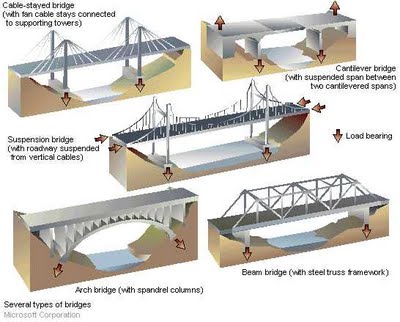
Or in this diagram, transitioning between a beam bridge and a suspension bridge in terms of forces. Although it's more like a simple catenary bridge, or the middle sagging cables of a suspension bridge, pulling on the towers, but without the anchors on the outside.
 
Thanks Mick... Do we know how hot and therefore how weak the trusses became? Is the weakness from heat a reduced compression strength or tensile strength or both? I can't image a softened steel sagging having much tensile strength... to pull the cool facade inward. I have no idea of the strength properties of hot steel which has slumped or sagged or softened. My gut tells me as it gets hotter enough to sag..it's not going to do much pushing or pulling. And whatever "happened" it was at the END of the period of heating.

No?

Perhaps unintuitive, but the weaker it gets, the more it will pull.

So long as it does not snap, then the entire weight of the truss is carried by the ends. But as it becomes weaker it becomes less rigid (both compressive and tensile] then it become more like a heavy rope or chain, and the forces act less straight down at the end supports, and more inwards.

Imagine a chain strung between two points, say two eyebolts screwed into opposite walls in a room. You can intuitively see it's pulling at those points, pulling the walls inwards.

Now imagine taking that chain, and welding all the links together so it is instead a straight rigid rod. Now you can take that same chain and simply rest it on top of the eyebolts (so they are like seated connections). Since it's rigid, there's no inward pulling.

Taking it a bit further, imagine you take a sagging chain, and weld that together so it's rigid structure, then even though it is curved, you can still rest it on the eyebolts (seats) and have no inward pulling force (in fact, based on the angle of contact, you could have an outward pushing force!).

The inward force does not come from the shape of the sagging beams. It comes from the lack of rigidity.
 
Nonsense... To bow (bend) a steel column assembly like those sections on floor 74 would take a rather substantial force.. even to move them a few millimeters.. And even if they did bow a few mm they would not then proceed to bow 55".
The bending... IB of those columns was from loading which exceeded there capacity and the direction was inward because there was an asymmetric lateral forces presented by the floor systems on that side.... which were sagging and so as OZ mentioned exerting a lateral force. The direction... IB and opposed to OB was driven by the floor system.. but no induced or caused by sagging. That is frankly pretty absurd.

Suppose you over loaded the floors and they began to deflect down. They would also bend and the catenary would create a lateral pull in at the columns. The more the load...the more the bow down and the more the lateral force. Fine.

But there was no additional loads on the floors... the lateral forces were only from the elongation. So I ask again... was the bow caused by the elongated floors being restrained by the stiff pinned ends... or was it the result of sagging and not elongated but therefore pulling inward. If you push down on cold truss they will sag/bow, but not elongate... and when they did... like pulling the tension line on a bow the bow bends as the line is pulled... they can pull inward.

If they are heated and elongated they push, if they are cold and the sag (not change length) they pull.

Take your pick.
Not sure if you are following what I am proposing.
The trusses sag. They are a lateral load on the perimeter column just as a weighted rope between core and perimeter would be.
YES, bending IS from overload axially BUT inwards preferential direction is due to cantilever forces due to sagging floors.

At first sag is due to constraints on the trusses. Once it gets hotter though, its not pushing , all deformation is in the sag.
 
I suspect that the vast majority of the member of AE911 don't really understand the mechanism being described here. It might be worth attempting some kind of infographic or animation to explain it. Or maybe some physical demonstration.
 
I suspect that the vast majority of the member of AE911 don't really understand the mechanism being described here. It might be worth attempting some kind of infographic or animation to explain it. Or maybe some physical demonstration.
A physical demo of what?

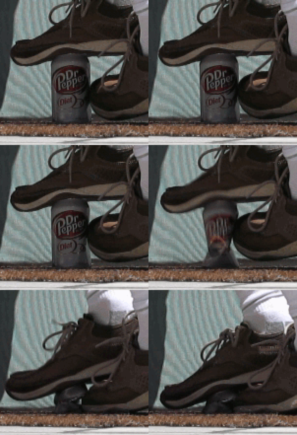
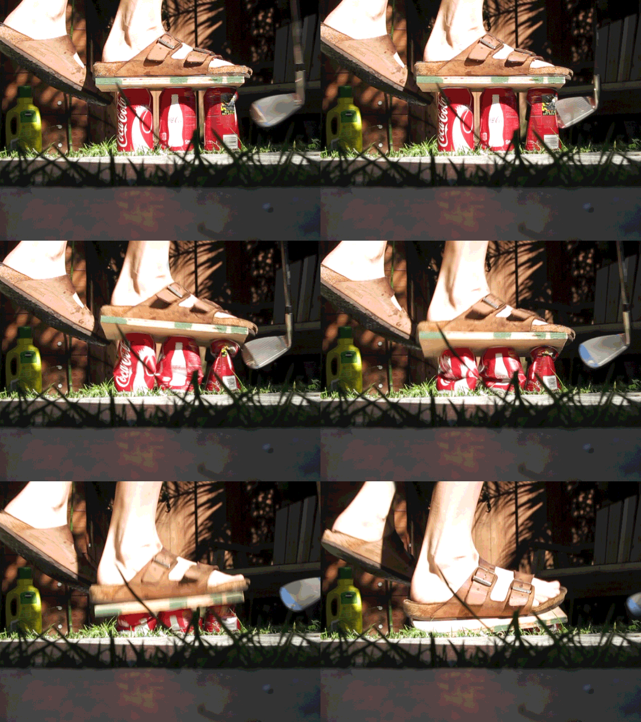
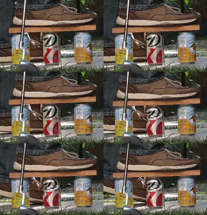
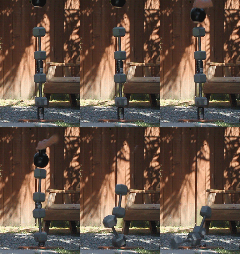
From school days back in the 80s I remember a vivid demonstration of how a tiny lateral tug on a vertical support can bring the vertical support from "stable" to "crushed" in an instance:

- Place an empty soda/beer can upright on the ground
- Carefully step on it with one foot flat on the top
- (Hopefully) the can can bear your weight (In the 80s, with my weight somewhat less and cans possibly a bit sturdier than today, they did; not sure if that still works today...)
- Carefully bow down and reach under your feet with your hands. That takes some amount of gymnastic talent :D
- Tip very lightly on the side of the can
- The can will stop bearing your weight and be crushed completely flat faster than you can blink your eye!
 
...Imagine a chain strung between two points, say two eyebolts screwed into opposite walls in a room. You can intuitively see it's pulling at those points, pulling the walls inwards....
And the point of further relevance here - the inwards force will be a multiple of the applied force. Depending on how close to straight the chain was at the start that multiple can be many times. Pure geometry of the vectors.

If you start with the chain taut then a sideways push could move the walls inwards. - possibly even to failure if the walls were non-structural partitions. Whilst the same push directly applied to the wall would have near zero effect.

That multiplier aspect goes to one of Jeffrey Orling's 'gut feeling' concerns - that there wouldn't be enough force from one sagging floor. As I once said in explanation to Tony Szamboti "Catenary sag is an effective force multiplier" - he accepted it but several others - both sides of the fence - gave me some argument. Which led me to claim "I could explain it to my Grandson" - and now leads me to your comment Mick:
I suspect that the vast majority of the member of AE911 don't really understand the mechanism being described here. It might be worth attempting some kind of infographic or animation to explain it. Or maybe some physical demonstration.
The challenge for most models is to get them close enough for the target audience to translate model>>reality. Not easy when the target audience includes people who cannot visualise the situation in the first place.

This is the "catenary pull in" model and experiment I conducted:

The "quantified" results:
1) One 6yo boy push at centre of rope caused 90-100mm IB of the far 'Perimeter Column'
2) The same 6yo push applied directly to the 'perimeter column' produced no measurable deflection.

The results confirmed by interview of the leading participant. With a language concession changing 'perimeter column' to 'tree' given the age and vocabulary limitations of said participant.

Even translating from horizontal to vertical mode caused some persons confusion. Those who originally disagreed counter claimed that the experiment was 'childish' and ignored that it proved the point. ;)
 
Last edited:
Perhaps unintuitive, but the weaker it gets, the more it will pull.

So long as it does not snap, then the entire weight of the truss is carried by the ends. But as it becomes weaker it becomes less rigid (both compressive and tensile] then it become more like a heavy rope or chain, and the forces act less straight down at the end supports, and more inwards.

I should qualify this a little, the maximum pull force would be for a taut yet flexible truss. As it sags more then the angle of pull becomes less horizontal, so there's more downwards force. So saying "the weaker it gets, the more it will pull." is not entirely correct, as you have to also account for the change in angle.
 
And the point of further relevance here - the inwards force will be a multiple of the applied force. Depending on how close to straight the chain was at the start that multiple can be many times. Pure geometry of the vectors.
...
In the summer of 2011, my girl friend and I bought a couple of hammocks, which we planned to attach to the steel rail around my roof-top terrace. We needed to buy some extra rope for both ends of each hammock, and the flimsy stuff she bought at a home improvement store inspired me to this thread at JREF:
http://www.internationalskeptics.com/forums/showthread.php?t=211653

Somewhere along the thread I lost sight of the math, but it's clear that for a rope/chain/joist that sags by only a liiiittle bit, the lateral pull is many many times the vertical load on the hammock/floor. And hammock-style demonstrations should be easy to do.
 
The beer can demo is very cool. But it's not analogous the the facade column structure. Regardless Mick taps the side of the can... and it crushes... this is not what we saw... we saw buckling not crushing.... and it appears to me that the buckling as as severe as it was because the top and the bottom of the panels were retrained (pinned). The facade buckled inward because of the side applied load of the floors.

I'd like to see a maxwell force diagram rather than crushed beer cans and a rope slung between two trees. We know that the rope is a fixed length and so when you pull it the ends move toward each other... DUH. And there is force caused by a flexible tension member going into catenary. I use this to retrieve an anchor with chain... The chain assumes a catenary. If you wind in some of the chain it first straightens out taught. But the weight of the chain makes it assume a catenary and it pulls at the anchor and the boat. The anchor is fast so the boat moves toward the anchor. RInse repeat and the boat is making way toward the anchor and you "easily" wind in the chain.... until the bow is over the anchor, it breaks free and can be raised easily.

I am still having trouble with the magnitude of the forces here and why a X ton load of a dead flat floor is different from an X ton load of a floor supported on a sagging beam...each sitting on a bearing plate weld to the side of a column.
 
In the summer of 2011, my girl friend and I bought a couple of hammocks, which we planned to attach to the steel rail around my roof-top terrace...
...but it's clear that for a rope/chain/joist that sags by only a liiiittle bit, the lateral pull is many many times the vertical load on the hammock/floor. And hammock-style demonstrations should be easy to do.
Another great example Oystein. AND you did it without any exploiting of Grandchildren. :rolleyes:
The chain assumes a catenary. If you wind in some of the chain it first straightens out taught. But the weight of the chain makes it assume a catenary and it pulls at the anchor and the boat. The anchor is fast so the boat moves toward the anchor. RInse repeat and the boat is making way toward the anchor and you "easily" wind in the chain....
yet another example. My usual example is extracting a bogged car - tie a rope tautly from the end of the car to a suitably located tree. Push sideways on rope. Car moves. Re-tighten rope and repeat.

Only problem being in most parts of AU where I get bogged the nearest tree... is................. ..........................way.....................over.............................there.
 
The beer can demo is very cool. But it's not analogous the the facade column structure. Regardless Mick taps the side of the can... and it crushes... this is not what we saw... we saw buckling not crushing.... and it appears to me that the buckling as as severe as it was because the top and the bottom of the panels were retrained (pinned). The facade buckled inward because of the side applied load of the floors.

I'd like to see a maxwell force diagram rather than crushed beer cans and a rope slung between two trees. We know that the rope is a fixed length and so when you pull it the ends move toward each other... DUH. And there is force caused by a flexible tension member going into catenary. I use this to retrieve an anchor with chain... The chain assumes a catenary. If you wind in some of the chain it first straightens out taught. But the weight of the chain makes it assume a catenary and it pulls at the anchor and the boat. The anchor is fast so the boat moves toward the anchor. RInse repeat and the boat is making way toward the anchor and you "easily" wind in the chain.... until the bow is over the anchor, it breaks free and can be raised easily.

I am still having trouble with the magnitude of the forces here and why a X ton load of a dead flat floor is different from an X ton load of a floor supported on a sagging beam...each sitting on a bearing plate weld to the side of a column.
The can demo was for WTC7

Ropes are not fixed length, they stretch.

It's not about flat or sagging, it's about rigid or flexible. Look back to my welded chain example. Or consider the difference in forces between a rigid truss between two points, and a chain of equal weight between two points. The truss has no pulling force, the heavy chain has a huge pulling force.
 
Back
Top